Process for the preparation of synthesis gas

a technology of synthesis gas and process, which is applied in the direction of lighting and heating apparatus, physical/chemical process catalysts, energy input, etc., can solve the problems of time-consuming and expensive replacement of spent catalyst, affecting and reducing the activity of catalysts at long intervals. , to achieve the effect of improving the utilisation of heat content in the flue gas and easy catalyst replacemen

Active Publication Date: 2006-08-08
HALDOR TOPSOE AS
View PDF36 Cites 8 Cited by
  • Summary
  • Abstract
  • Description
  • Claims
  • Application Information

AI Technical Summary

Benefits of technology

[0020]The process of the invention solves the problems occurring with the prior art by providing an improved process including the step of steam and / or CO2 reforming a hydrocarbon steam mixture in contact with a solid catalyst having activity in steam reforming. The solid catalyst, for instance catalysed hardware, is arranged in piping system of a flue gas heated coil system constituting a steam reforming unit. Subsequently, the effluent from the steam reforming unit is contacted with a steam reforming catalyst in a fired steam reformer. By locating some or all of the steam reforming catalyst of the steam reforming unit as removable structured catalysts in adiabatic zones of the piping system of the heated coil system outside the flue gas channel easy catalyst replacement is achieved, while at the same time achieving improved utilisation of the heat content in the flue gas for steam reforming.

Problems solved by technology

The main disadvantage of this process is decreasing catalyst activity at long time operation of the catalysed preheater coil.
Replacement of catalyst in the pre-heater coil is a difficult and expensive operation when demounting the coil from the flue gas channel.
As mentioned earlier replacement of spent catalyst applied as a thin film to a coil within the flue gas channel is time consuming and expensive to handle.
This results in an increased outlet temperature from the coil.
However, as the deactivation of the catalyst in the catalysed pre-heater coil becomes severe the resulting temperature increase becomes a problem.
The temperature of the pre-heater coil increases, which may exceed design temperatures, resulting in a smaller driving force for heat transfer from the flue gas leading to a smaller transferred duty, with the consequence that the capacity of the total reforming system has decreased.
The use of the intermediate reforming unit does not solve these issues, and replacement of the thin film catalyst applied to the wall of the pre-heater coil becomes necessary.
The processes described in EP 855,366 and EP 1,069,070 both have the disadvantage of difficult replacement of the thin film catalyst on the wall of the catalysed pre-heater coil in the flue gas channel.
However, deactivation of the thin film catalyst on the wall of the reheat coil in the waste heat section is expected with time to eventually necessitate replacement of this catalyst.
As explained above this operation undesirable as it is time consuming and expensive.
However, the use of many adiabatic reactor vessels is overall an expensive solution.
However, heat exchange in counter current flow between the flue gas and the reforming tube is poor.
Despite this the amount of heat transfer possible is relatively limited if the reformer tube length is to be kept at a reasonable length.

Method used


Image

  • Process for the preparation of synthesis gas
  • Process for the preparation of synthesis gas
  • Process for the preparation of synthesis gas

Examples


example 1

[0060]A comparison of the amount of catalyst required in a process of the invention as compared to a conventional process was made.

[0061]The conventional process was carried out by feeding hydrocarbon and steam into a pre-reformer followed by heating in a coil in the flue gas-containing waste heat section of a tubular reformer. Initially the feed was heated prior to passage through the first adiabatic reactor containing steam reforming catalyst pellets. Subsequently, the mixture was reheated and reacted again, the number of reheating and reaction steps repeated until four reheating steps and four reaction steps altogether had been carried out.

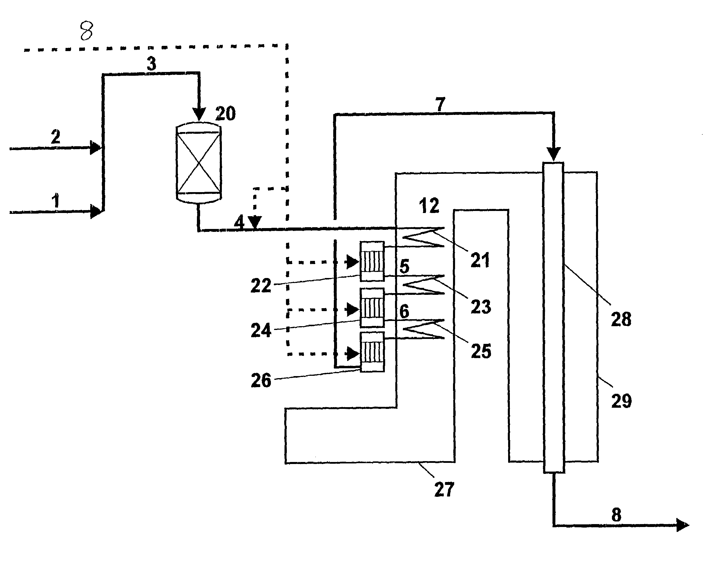
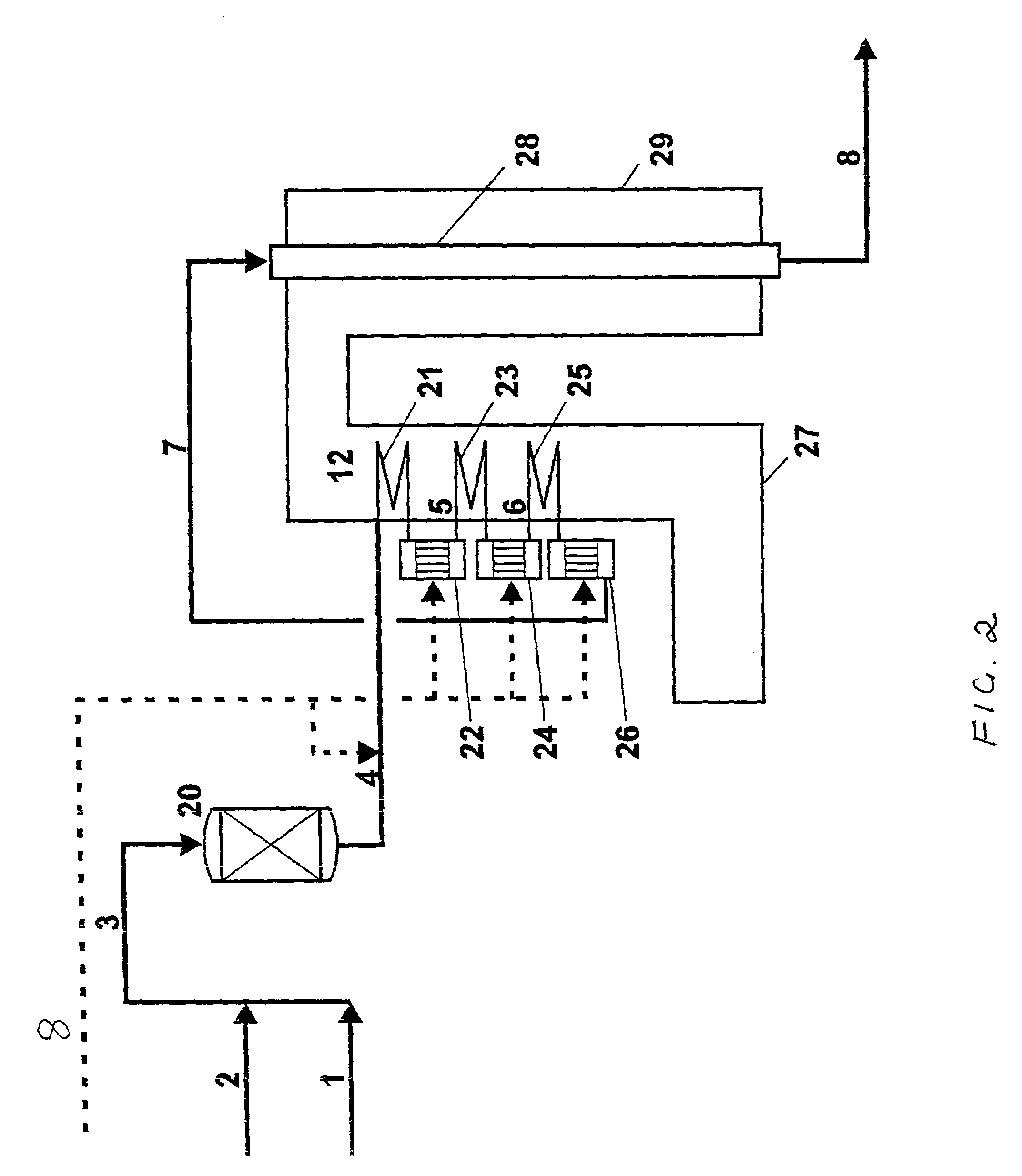
[0062]In the a process of the invention a feed consisting of hydrocarbon and steam was fed into a pre-reformer followed by passage through a piping system in the flue gas-containing waste heat section of a tubular reformer. Initially the feed was heated prior to passage through the first adiabatic header system containing a catalysed structured...

example 2

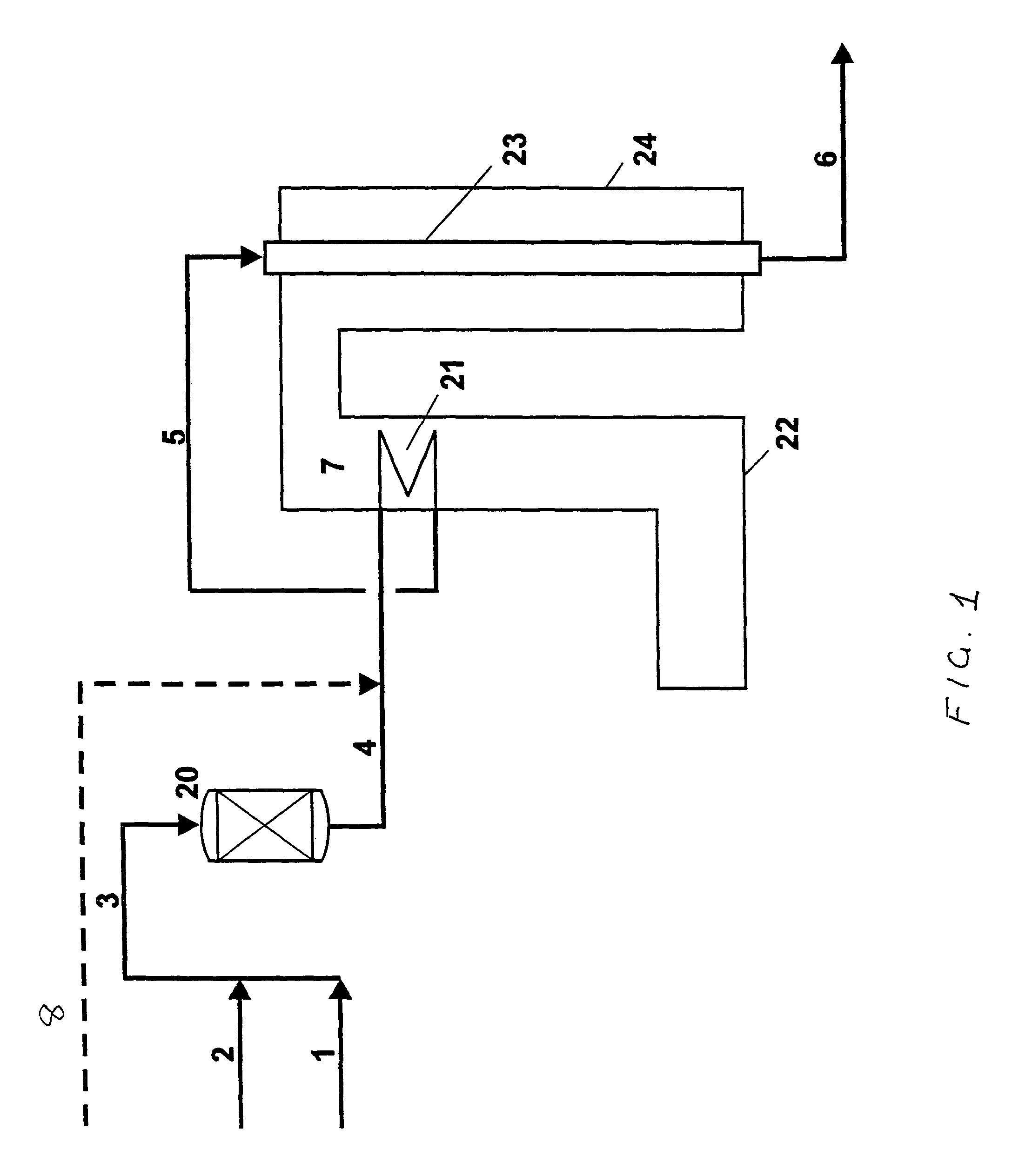
[0066]This example is based on the systems described in FIGS. 1 and 2, without CO2 addition. A waste heat boiler was placed in the flue gas section of the reformer, required in order to obtain overall high energy efficiency by recovering the heat content in the flue gas.

[0067]The figures shown in Table 2 indicate that substantial savings are obtainable using the process of the invention.

[0068]

TABLE 2Comparison of the duty distribution ina Conventional process compared withprocess of the inventionConventionalInventionPrimary reformer duty,40.322.6Gcal / hReheat coil duty,5.3n.a.Gcal / hReheat coil / headern.a.12.0system with structurecatalyst duty, Gcal / hTotal Reforming Duty,45.645.6Gcal / hFlue Gas Flow, Nm3 / h10516692054Waste heat boiler9.82.0duty, Gcal / h

[0069]The results showed that the duty required by the reformer was much less in the case where the process of the invention was used. A smaller reformer can therefore be used in the process of the invention. The amount of steam generated w...


PUM

PropertyMeasurementUnit
temperatureaaaaaaaaaa
inlet temperatureaaaaaaaaaa

Abstract

Process and apparatus for the preparation of synthesis gas by catalytic steam and/or CO2 reforming of a hydrocarbon feedstock comprising the following steps:
    • (a) heating the reaction mixture of hydrocarbon feedstock and steam and/or CO2 in the flue gas containing waste heat section from the fired tubular reformer
    • (b) adiabatic reforming of the reaction mixture outside the waste heat section by contact with a solid reforming catalyst
    • (c) repeating steps (a) and (b) until the desired reaction mixture composition and temperature is reached
    • (d) feeding the reaction mixture to the fired tubular reformer and further reforming the mixture to the desired composition and temperature,
    • wherein the adiabatic reforming of the reaction mixture is conducted in the process gas piping system in the flue gas-containing waste heat section, the piping system having adiabatic zones outside the heating section and containing solid reforming catalysts comprising one or more catalyzed structured elements.

Description

BACKGROUND OF THE INVENTION[0001]1. Field of the Invention:[0002]The present invention relates to a process and an apparatus for the preparation of synthesis gas. The preparation process includes catalytic steam and / or carbon dioxide reforming of a hydrocarbon feedstock. In particular, the invention provides an improved process of the above type including the steps of heated steam reforming of a hydrocarbon steam mixture in contact with catalysed hardware having activity in steam reforming and subsequently reforming the partially reformed effluent in a fired steam reformer.[0003]2. Description of the Related Art:[0004]Partial steam reforming upstream of a fired steam reformer in the form of pre-reforming of a hydrocarbon feedstock in the preparation of synthesis gas is well known in the art. Pre-reforming is generally employed with hydrocarbon feed containing higher hydrocarbons or for increasing the capacity of the existing reformer plants. Process gas of the hydrocarbon feedstock ...

Claims


Application Information

Patent Timeline
Patent Type & Authority Patents(United States)
IPC IPC(8): C01B3/38C10L3/08
CPCC01B3/382C01B3/384C01B2203/0233C01B2203/142C01B2203/1011C01B2203/1023C01B2203/1035C01B2203/0816Y02P20/129C10L3/08
Inventor ROSTRUP-NIELSEN, THOMASERIKSTRUP, NIELSCHRISTENSEN, PETER SEIERAASBERG-PETERSEN, KIMHANSEN, JENS-HENRIK BAKDYBKJAER, IB
Owner HALDOR TOPSOE AS
Why Eureka
Try Eureka