
Fuel cell operation method

a fuel cell and operation method technology, applied in the direction of fuel cell control, fuel cell, solid electrolyte fuel cells, etc., can solve the problems of difficult to completely seal in, difficult to prevent hydrogen leakage, difficult to completely block the hydrogen from leaking out of the fuel cell, etc., to achieve the effect of increasing the operating pressure and preventing hydrogen leakag

Inactive Publication Date: 2006-08-08
HONDA MOTOR CO LTD
View PDF3 Cites 11 Cited by
  • Summary
  • Abstract
  • Description
  • Claims
  • Application Information

AI Technical Summary

Benefits of technology

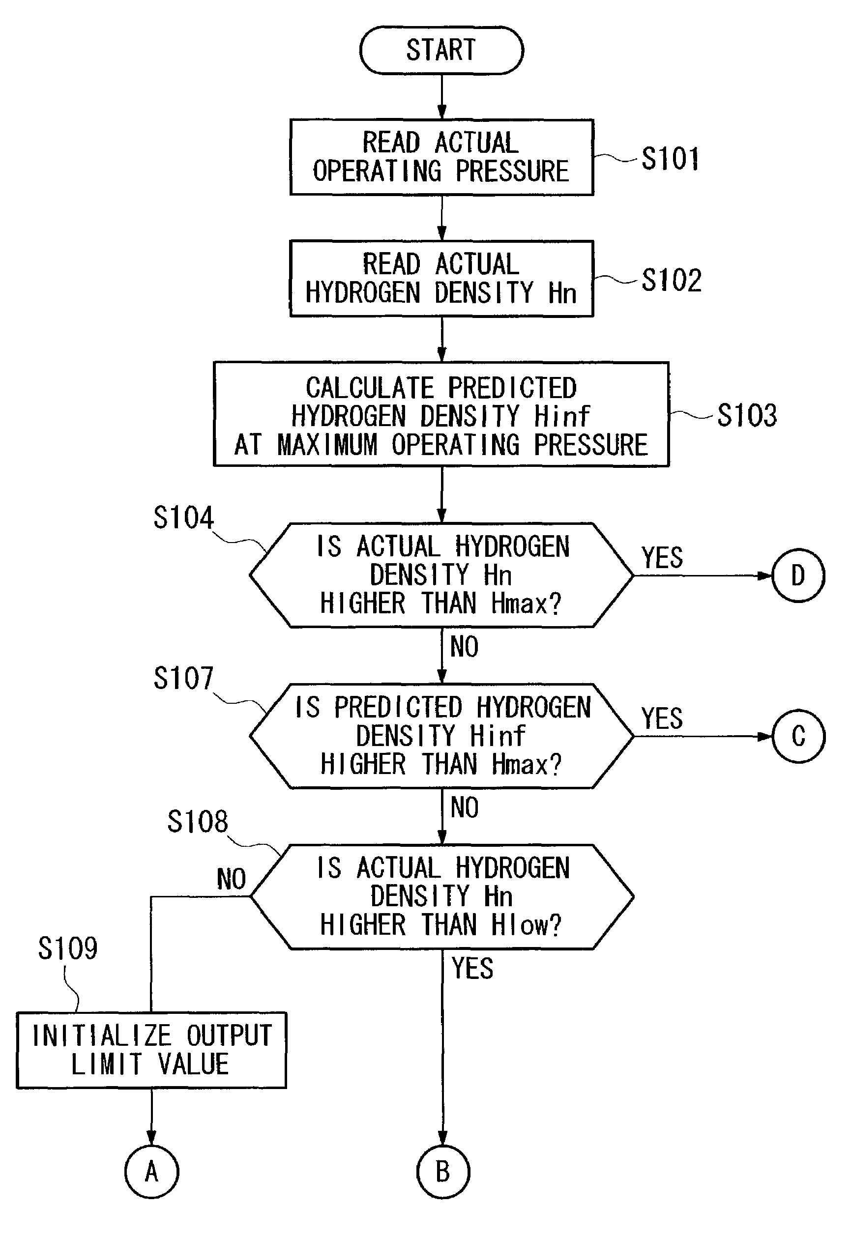
[0010]Therefore, the present invention provides a fuel cell operation method that makes use of the feature that the amount of hydrogen leakage from a fuel cell has a correlation with the operating pressure of the fuel cell (namely, with the reaction gas supply pressure) so that the higher the operating pressure the greater the amount of hydrogen leakage, and that limits the operating pressure such that the amount of hydrogen leakage from the fuel cell does not exceed a predetermined value.
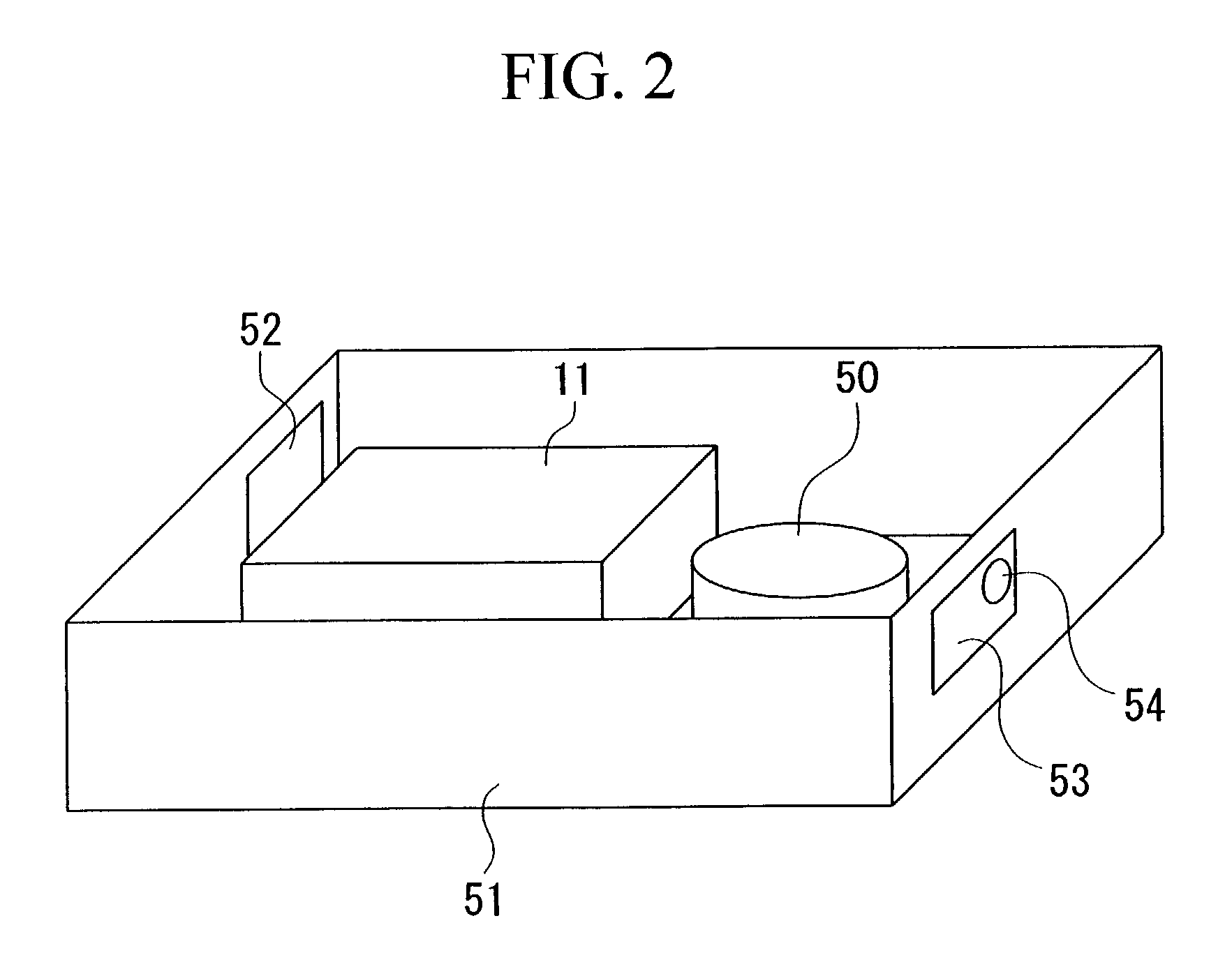
[0012]When the ventilation amount in the vicinity of a fuel cell is constant, a correlation exists between the amount of hydrogen leaking from the fuel cell and the hydrogen density in the vicinity of the fuel cell. Accordingly, it is possible to estimate the hydrogen leakage amount from the fuel cell based on values detected by a hydrogen sensor. Moreover, the characteristic exists that the hydrogen leakage amount from the fuel cell depends on the operating pressure of the fuel cell (namely, the supply pressure at which reaction gas is supplied), and the higher the operating pressure the greater the hydrogen leakage amount. Accordingly, it is possible to control the operation of the fuel cell by limiting the operating pressure such that the hydrogen leakage amount from the fuel cell does not exceed a predetermined value based on values detected by the hydrogen sensor.

Problems solved by technology

However, because hydrogen is a highly permeating substance it is extremely difficult to seal it in completely.
In particular, because the above described solid polymer electrolytic membrane type of fuel cell has a stack structure it is difficult to completely block the hydrogen from leaking out from the fuel cell.
Moreover, it is difficult to prevent hydrogen leakages from joint portions such as where connections are formed in the hydrogen piping.
However, in a system such as the conventional one in which a warning is issued and the system halted when a predetermined hydrogen density is detected by the hydrogen sensor there are times when the system is suddenly halted without any prior warning.
In the case of a fuel cell vehicle, if the operation of the fuel cell is suddenly halted like this the problem arises that the vehicle cannot be moved to a location where repairs can be made.
Moreover, as is disclosed in Japanese Patent Application Laid-Open (JP-A) No. 8-31436, in a system in which a ventilation fan is operated and the interior of the box is forcibly ventilated when a predetermined hydrogen density is detected by the hydrogen sensor, because the amount of hydrogen leakage is not suppressed the fear arises that the amount of hydrogen leakage will subsequently continue to increase.

Method used


Image

  • Fuel cell operation method
  • Fuel cell operation method
  • Fuel cell operation method

Examples


Embodiment Construction

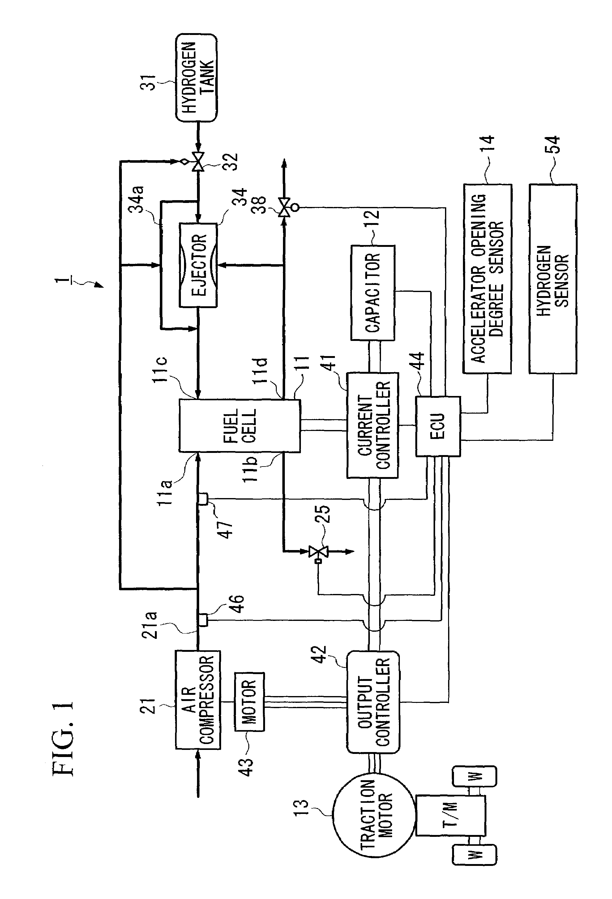
[0022]An embodiment of the fuel cell operation method of the present invention will now be described with reference to FIGS. 1 to 7. Note that the embodiment in this case is applied to a fuel cell mounted in a fuel cell vehicle.

[0023]FIG. 1 is a schematic structural view of a fuel cell vehicle.

[0024]The fuel cell vehicle 1 is provided with a hybrid type of power unit formed by a fuel cell 11 and a storage apparatus, for example, the capacitor 12. The drive force of a traction motor 13 to which power is supplied from this power unit is transmitted to driving wheels W via a transmission T / M formed either by an automatic transmission or a manual transmission.

[0025]When drive force is transmitted from the driving wheel W side to the traction motor 13 side as the vehicle is decelerating, the traction motor 13 functions as a power generator to generate what is known as regenerative braking force, and thereby recover the kinetic energy of the vehicle as electrical energy.

[0026]The fuel cel...


PUM

PropertyMeasurementUnit
pressuresaaaaaaaaaa
hydrogen densityaaaaaaaaaa
operating pressureaaaaaaaaaa

Abstract

The present invention relates to a fuel cell operation method in which a fuel cell 11 that generates power using hydrogen gas and oxidant gas as reaction gas is operated at an operating pressure that corresponds to a required power generation state. A hydrogen sensor 54 that detects hydrogen density is provided in a vicinity of the fuel cell 11, and based on values detected by the hydrogen sensor 54 and on the amount of hydrogen leakage at the current operating pressure and on the characteristics of the fuel cell 11, an operating pressure is predicted at which the hydrogen leakage amount from the fuel cell will not exceed a predetermined value, and the fuel cell 11 is operated while limiting the operating pressure to below the predicted operating pressure.

Description

BACKGROUND OF THE INVENTION[0001]1. Field of the Invention[0002]The present invention relates to an operation method for a fuel cell that generates electricity using hydrogen gas and oxidant gas as reaction gases, and, in particular, to an operation method for a fuel cell that has excellent safety control against hydrogen leakages.[0003]2. Description of the Related Art[0004]One type of fuel cell that is mounted in a fuel cell vehicle or the like is formed as a stack in which a plurality of cells, each formed by interposing between an anode and a cathode a solid polymer electrolytic membrane (formed, for example, from a solid polymer ion exchange membrane or the like) such that the solid polymer electrolytic membrane is sandwiched on both sides by the anode and cathode, are arranged in layers. This fuel cell is provided with a hydrogen pole to which hydrogen gas is supplied as fuel gas, and an air pole to which air containing oxygen is supplied as an oxidant gas. In this fuel cell h...

Claims


Application Information

Patent Timeline
Patent Type & Authority Patents(United States)
IPC IPC(8): H01M8/04H01M8/10
CPCH01M8/04089H01M8/04223Y02E60/50H01M8/241H01M8/2457H01M8/04298
Inventor SUGINO, TAKUYASUZUKI, JUNNAKAJIMA, NOBUTAKA
Owner HONDA MOTOR CO LTD
Learn More