

Display device
a technology of display device and display image, which is applied in the direction of picture reproducers using projection devices, static indicating devices, instruments, etc., can solve the problems of low cost manufacturing of display devices, image quality degradation (liner defects), and basic problems, so as to achieve easy realization of high definition of display images, increase the number of spatial light modulation elements, and increase the number of pixels
- Summary
- Abstract
- Description
- Claims
- Application Information
AI Technical Summary
Benefits of technology
Problems solved by technology
Method used
Image

Examples
first embodiment
(A First Embodiment)
(Structure of Laser Display Device)
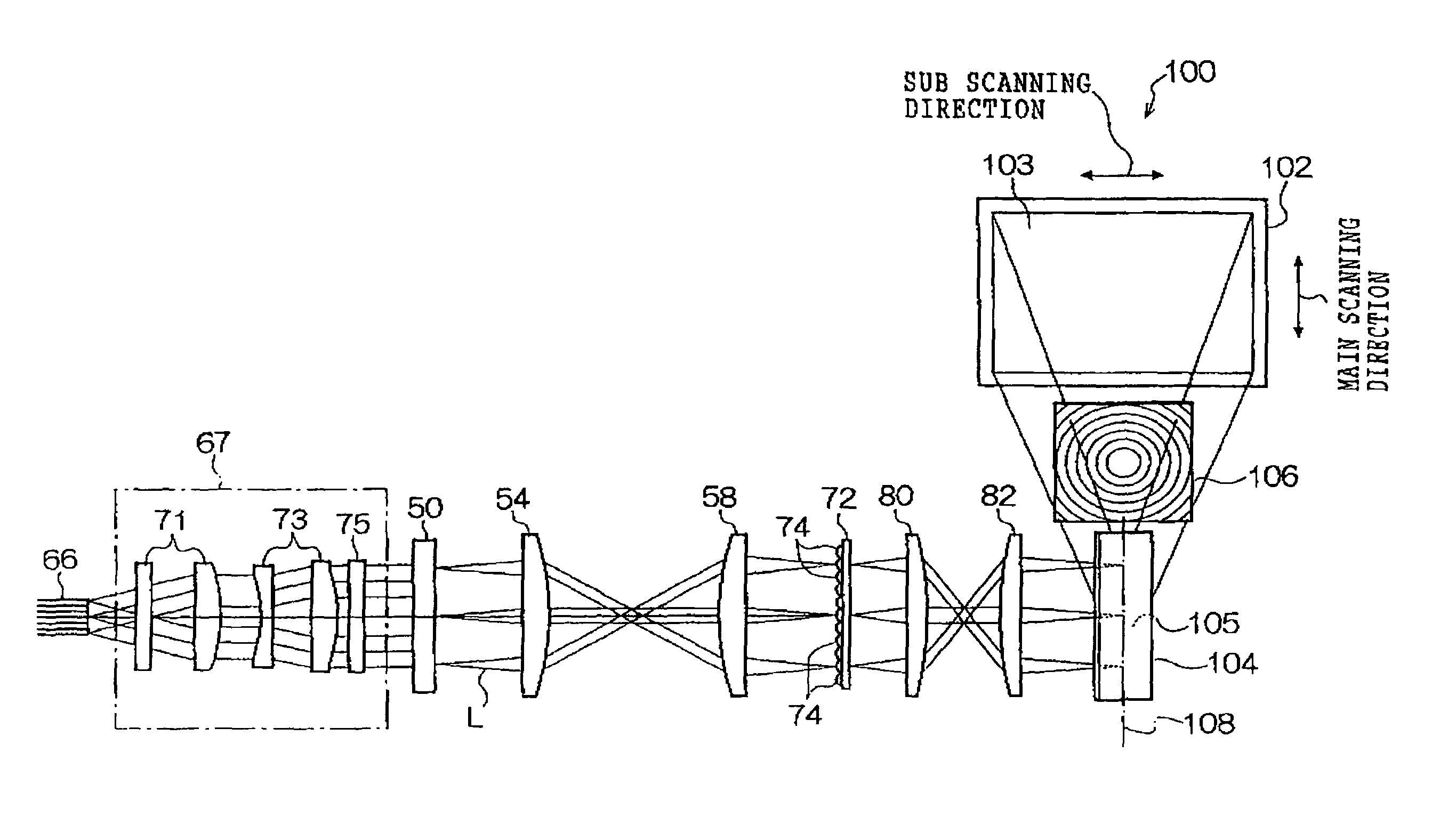
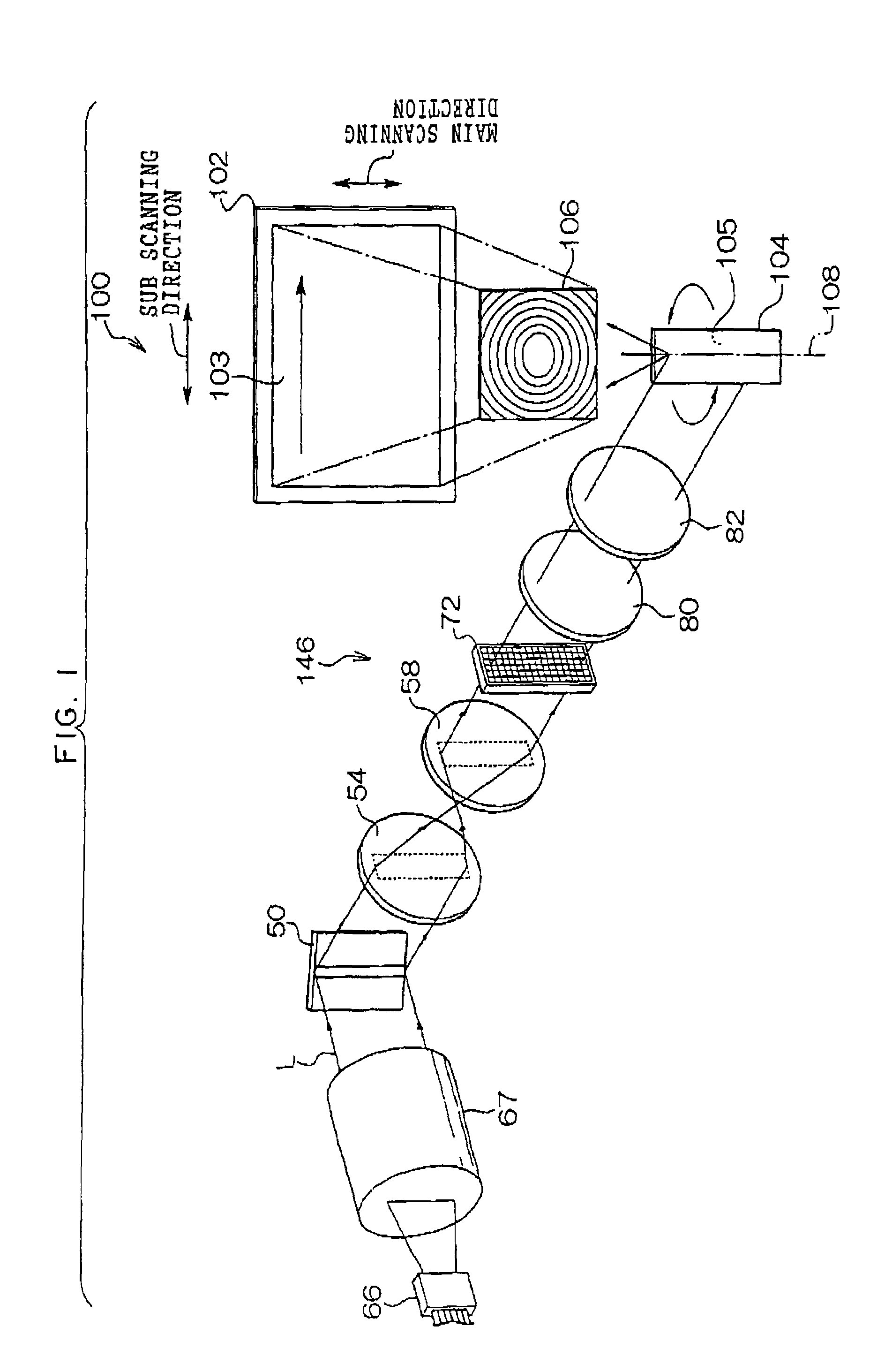
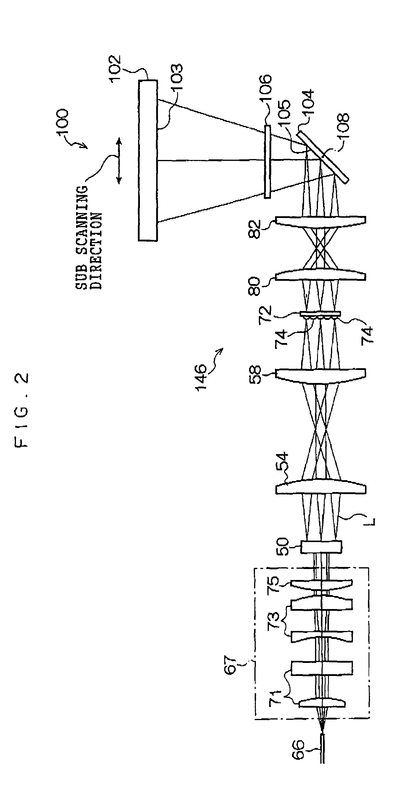
[0065]In each of FIGS. 1, 2 and 3, a laser display device related to a first embodiment of the present invention is shown. The laser display device 100 is constructed as a projector type device for which a monochrome image is projected and displayed on an image display surface 103 of a screen 102, by the image display surface 103 of the screen 102 being directly scanned by a laser beam L.
[0066]As shown in FIG. 1, the laser display device 100 is provided with a fiber array light source 66 which serves as a light source device of the laser beam L. On an optical path of the laser beam L emitted from the fiber array light source 66, an illumination optical system 67, a digital micro mirror device (DMD) 50, an imaging (image forming) optical system 146, a galvano mirror 104, and a Fresnel lens 106 are disposed in that order from the fiber array light source 66 side.
[0067]The laser display device 100 is provided with a controller (not...
second embodiment
(A Second Embodiment)
[0125]A laser display device 110 related to the second embodiment of the present invention will be explained. In FIG. 16, the laser display device 110 related to the second embodiment of the present invention is shown. In the laser display device 110, an image display surface 137 of a screen 136 is directly scanned by a color laser beam LM in which a red laser beam LR, a green laser beam LG and a Blue laser beam LB are mixed. That is, the laser display device 110 is a projector-type device in which a color image is projected and displayed on the image display surface 137. Note that, in the laser display device 110 related to the second embodiment, the same reference numerals are applied to the same components, members and structures as those of the laser display device 100 related to the first embodiment and the descriptions thereof are omitted.
[0126]As shown in FIG. 16, the laser display device 110 is provided with three GaN semiconductor laser (hereinafter, LD...
third embodiment
(A Third Embodiment)
[0131]Next, description will be given of a laser display device 200 pertaining to a third embodiment of the invention. The laser display device 200 pertaining to the third embodiment of the invention is shown in FIG. 20. The laser display device 200 is a projector device in which an image display surface 103 of a screen 102 is directly scanned by laser beams L1, L2 and L3 (indicated below as “L1 to L3”) that are respectively modulated by the DMDs 208, 210 and 212, to the by project and display an image on the image display surface 103. The laser display device 200 is configured as a device particularly suited for displaying a moving image. It should be noted that, in the laser display device 200 pertaining to the third embodiment, portions shared in common with those of the laser display device 100 pertaining to the first embodiment will be given the same reference numerals and description of those portions will be omitted.
[0132]As shown in FIG. 20, three fiber a...
PUM
 Abstract
Description
Claims
Application Information