Image-capturing apparatus

a technology of image capture and imager, which is applied in the direction of television system, instrument, and control of exposure, etc., can solve the problems of insufficient reflected light, inability to return, and different scenes that are actually photographed, so as to reduce power consumption and low level

Inactive Publication Date: 2006-08-08
KONICA CORP
View PDF18 Cites 28 Cited by
  • Summary
  • Abstract
  • Description
  • Claims
  • Application Information

AI Technical Summary

Benefits of technology

[0013]To overcome the abovementioned drawbacks in conventional image-capturing apparatus, the first object of the present invention is to provide an

Problems solved by technology

Further, to cope with such a case that a sufficient reflected light cannot be returned from the subject when capturing images in a room or a night, the conventional electronic still cameras incorporate an automatic intensity-adjusting strobe.
On the other hand, when capturing a scene in which the subject brightness is currently varying, there is a fear that a field brightness at the stage of pushing the release switch to a half-stroke is different from that at the stage of pushing the release switch to a full-stroke, resulting in an inappropriate exposure amount.
In this case, since a time lag is generated between the time of pushing the release switch and the time of exposing the scene, there is a fear that the scene actually photographed is different from the scene that the photographer really intended to capture, due to a change of the subject posture within the time lag, etc.
It has been a problem, however, that the photometry element separately equipped in the camera would raise the cost of electronic still camera and would make the size of the camera larger.
Such the camera, however,

Method used


Image

  • Image-capturing apparatus
  • Image-capturing apparatus
  • Image-capturing apparatus

Examples


first embodiment

[0182]FIG. 10 shows a flowchart of operations of an electronic still camera, serving as the present invention.

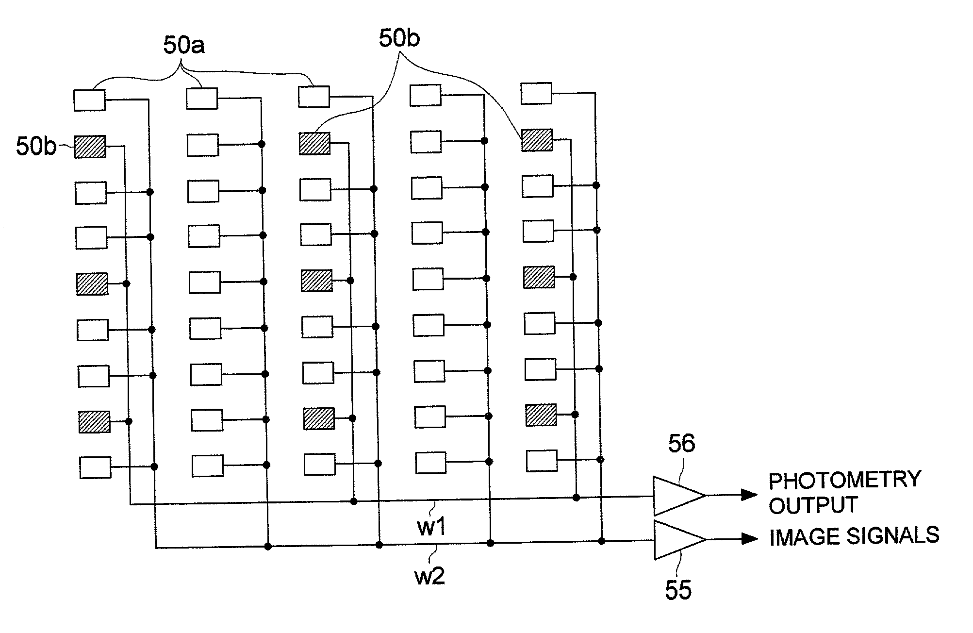
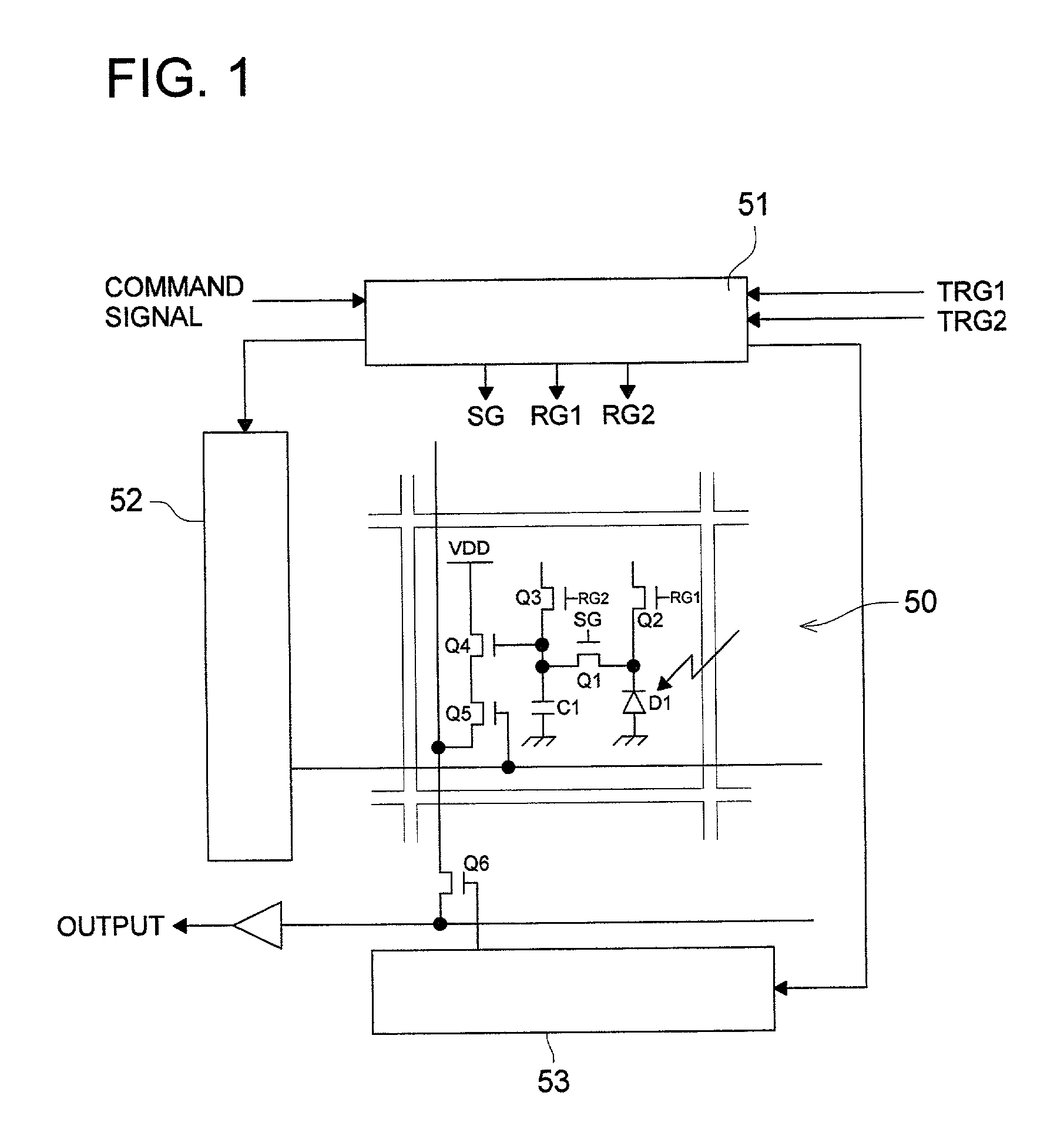
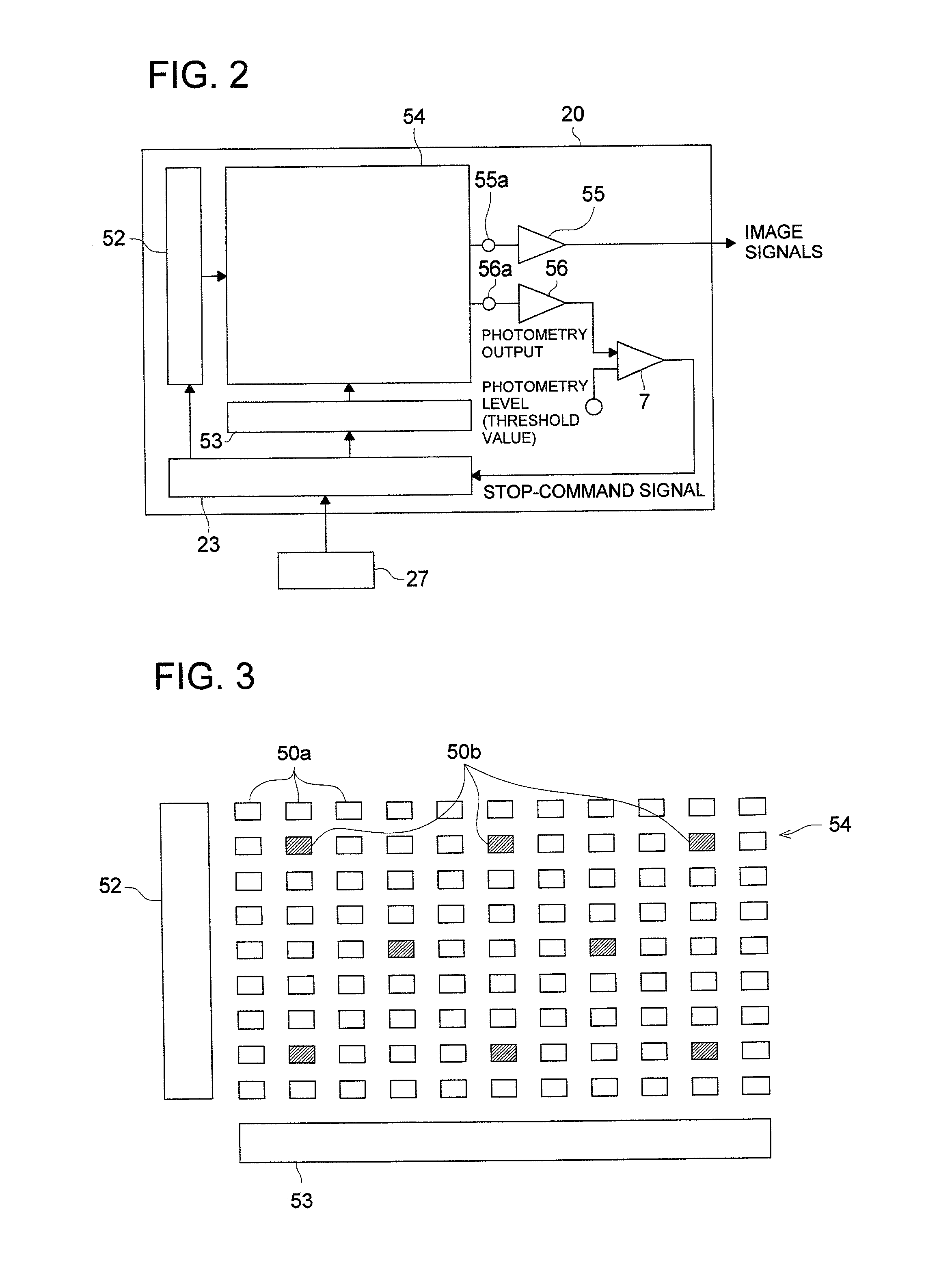
[0183]The flowchart shown in FIG. 10 comprises the steps of: S101, determining whether or not power switch 25 is turned ON; S102, supplying electronic power from battery BT to MPU 27, etc., when determining that power switch 25 is turned ON in step S101; S103, determining whether or not release switch 24 is pushed; S104, simultaneously commencing photo-electronic converting actions of first group circuit cells 50a, serving as first photo-electronic converting elements for capturing an image, and second group circuit cells 50b, serving as second photo-electronic converting elements for performing a photometry, under a command signal sent from MPU 27 when determining that release switch 24 is pushed in step S103; S105, determining whether or not the exposure amount reaches to a specific light amount (a predetermined value) by means of comparator 7, wherein MPU 27 sends command...

third embodiment

[0193]Further, in the third embodiment, half mirror 60 is disposed between photographic lens 1 and image-capturing section 54 to reflect a part of the light reflected from subject 3 in a direction orthogonal to the optical axis. The part of the light coming from half mirror 60 is further reflected by Mirror 61 so as to enter into photo-sensing element 250b. With respect to the exposure controlling method using the output signal of photo-sensing element 250b, explanations are omitted since such the method is the same as that of the aforementioned embodiment.

[0194]According to the third embodiment, since a general purpose CMOS imager can be employed for image-capturing section 54 including wirings for reading out the signals, it becomes possible to reduce a manufacturing cost of the electronic still camera more than that of a conventional one. Incidentally, half mirror 60 and mirror 61 constitute an optical system.

[0195]Although the embodiments of the present invention are detailed in...

fourth embodiment

[0197]FIG. 13 shows a simplified block diagram of a configuration of an electronic still camera, serving as the image-capturing apparatus embodied in the present invention. Numeral 27 indicates a microprocessor (MPU), which determines a degree of aperture, a shutter speed, etc., and outputs command signals to the various kinds of incorporated circuits, numeral 200 indicates a strobe circuit to drive a light emitting tube mounted in strobe 2 so that strobe 2 emits the strobe light in response to a triggering command signal (a light-emission starting signal) sent from MPU 27, numeral 21 indicates a photographic lens to focus the light reflected from subject 3, numeral 22 indicates a CMOS imager shown in FIG. 13. Numeral 23 indicates an imager controlling circuit, which receives stop-command signal from comparator 7, serving as a judging section, to controls the exposure amount of CMOS imager 22. Operations of the electronic still camera, having the configuration mentioned above, will ...


PUM


Abstract

The invention concerns an image-capturing apparatus and an imager. The image-capturing apparatus includes the imager in which a plurality of circuit cells are two-dimensionally aligned, and an electronic charge, photo-electronically converted from a received light and stored in each circuit cell, can be discharged from an arbitral circuit cell. The imager includes first group circuit cells to generate electronic charges corresponding to the pixels of the image including a subject, and second group circuit cells to generate electronic charges corresponding to an amount of light coming from the subject, the electronic charges further being converted to a detected value. In the imager, at least one of two operations of halting a generating-action of the electronic charges in the first group circuit cells and discharging the electronic charges from the first group circuit cells is performed, when the detected value exceeds a threshold value.

Description

BACKGROUND OF THE INVENTION[0001]The present invention relates to an image-capturing apparatus and an imager, and specifically relates to an image-capturing apparatus, such as an electronic still camera, etc., in which an electronic shutter function and a light detecting function of the solid-state imager is utilized for controlling an exposure amount, and an imager employed for the image-capturing apparatus.[0002]Thanks to the recent development of the electronic technology, electronic still cameras including digital still cameras, which can convert a photo-image to image data and can store the image data, have been developed and proliferated in the market. Incidentally, in the conventional electronic still cameras, a photometry conducted by the imager is commenced when the release switch is pushed to a half-stroke, and then, an image-capturing is conducted at a shutter speed and an aperture determined on the basis of the photometry result when the release switch is pushed to a ful...

Claims


Application Information

Patent Timeline
IPC IPC(8): H04N3/14H04N5/335H04N5/222H04N5/235H04N5/353H04N5/369H04N5/374H04N5/376
CPCH04N5/2351H04N5/2353H04N5/2354H04N5/376H04N5/3696H04N5/3741H04N5/353H04N23/71H04N23/73H04N23/74H04N25/53H04N25/702H04N25/766H04N25/74
Inventor TAKAYAMA, JUNTAKABA, TETSUFUMIMIYATA, KYOSEIHOSAKA, TAKAOKITADA, TAKENORISATO, KOICHIKIBAYASHI, HIROSHI
Owner KONICA CORP
Why Eureka
Try Eureka