Moving lens for immersion optical lithography

a technology of optical lithography and moving lens, which is applied in the field of optical lithography, can solve the problems of increasing the complexity of the problem, the computational requirements of the application used, and the manufacturers' struggle to maintain the precision necessary for useful operation, etc., and achieves the effect of reducing turbulence and air bubbles, minimizing air bubbles, turbulence, and other disruptions

Inactive Publication Date: 2006-08-08
INT BUSINESS MASCH CORP
View PDF10 Cites 30 Cited by
  • Summary
  • Abstract
  • Description
  • Claims
  • Application Information

AI Technical Summary

Benefits of technology

[0013]The current invention reduces the turbulence and air bubbles associated with the relative motion of a final lens element in an immersion optical lithography environment. The lens apparatus is coupled to a motion control device capable of adjusting the final lens' angular orientation relative to the wafer. The current invention enables the lens apparatus to move such that the horizontal velocity of a portion of the final lens element relative to the wafer surface substantially minimizes air bubbles, turbulence, and other disruptions of said liquid detrimental to imaging quality as the wafer is scanned.

Problems solved by technology

As the complexity of the problems has increased, so too have the computational requirements of the applications used to solve these problems.
As wire, component, and layer density increased on computer chips, manufacturers struggled to maintain the necessary precision for useful operation.
Optical lithography has been extended to use 193 nanometers for manufacturing patterns, but problems begin to occur below this wavelength.
At this point, the implemented wavelength is no longer capable of printing the chip design with sufficient fidelity.
To overcome this problem, shorter light wavelengths must be used; however, new problems arise when using shorter wavelengths.
Shorter wavelengths, such as x-rays have been used to achieve smaller linewidths, but the adoption of equipment capable of producing x-rays has been hindered by difficulties associated with manufacturing lenses capable of producing sufficient imaging quality when used with x-rays.
These difficulties have led to high lens costs resulting in an expensive migration path from past optical lithography equipment to x-ray optical lithography equipment.
Shorter wavelengths are also higher energy wavelengths and therefore high doses of x-rays have a greater potential to damage the solid chip material, especially dielectric.
Furthermore, light sensitive compounds in resist only absorb light over a specific range of wavelengths and alternative materials may not always perform as well as necessary.
The use of a liquid in optical lithography increases the depth of focus by a factor equal to the index of the immersion liquid when NA is held constant, therefore increasing the tolerable error in the process.
The advent of immersion optical lithography has also resulted in numerous additional problems.
As the lens moves through the liquid, the motion of the lens translates energy from the lens into the liquid, thus creating ripples, turbulence, and disruption of the liquid environment.
Gas and air bubbles may become trapped within the liquid or attach to the lens surface resulting in light scattering and poor quality imaging.

Method used


Image

  • Moving lens for immersion optical lithography
  • Moving lens for immersion optical lithography
  • Moving lens for immersion optical lithography

Examples


Embodiment Construction

[0022]The invention will be described in detail with reference to the following figures. It will be appreciated that this description and these figures are for illustrative purposes only, and are not intended to limit the scope of the invention. In particular, various descriptions and illustrations of the applicability, use, and advantages of the invention are exemplary only, and do not define the scope of the invention. Accordingly, all questions of scope must be resolved only from claims set forth elsewhere in this disclosure.

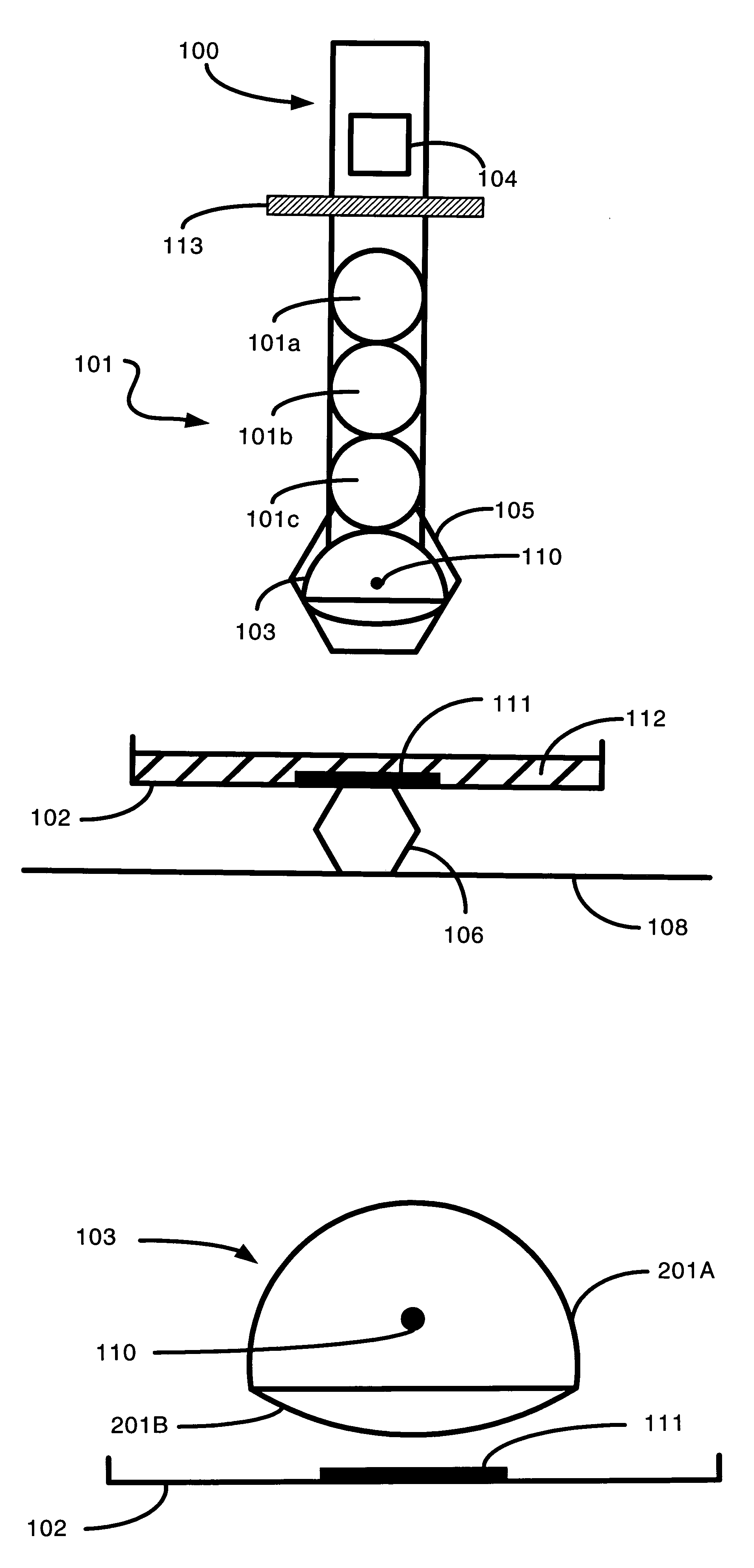
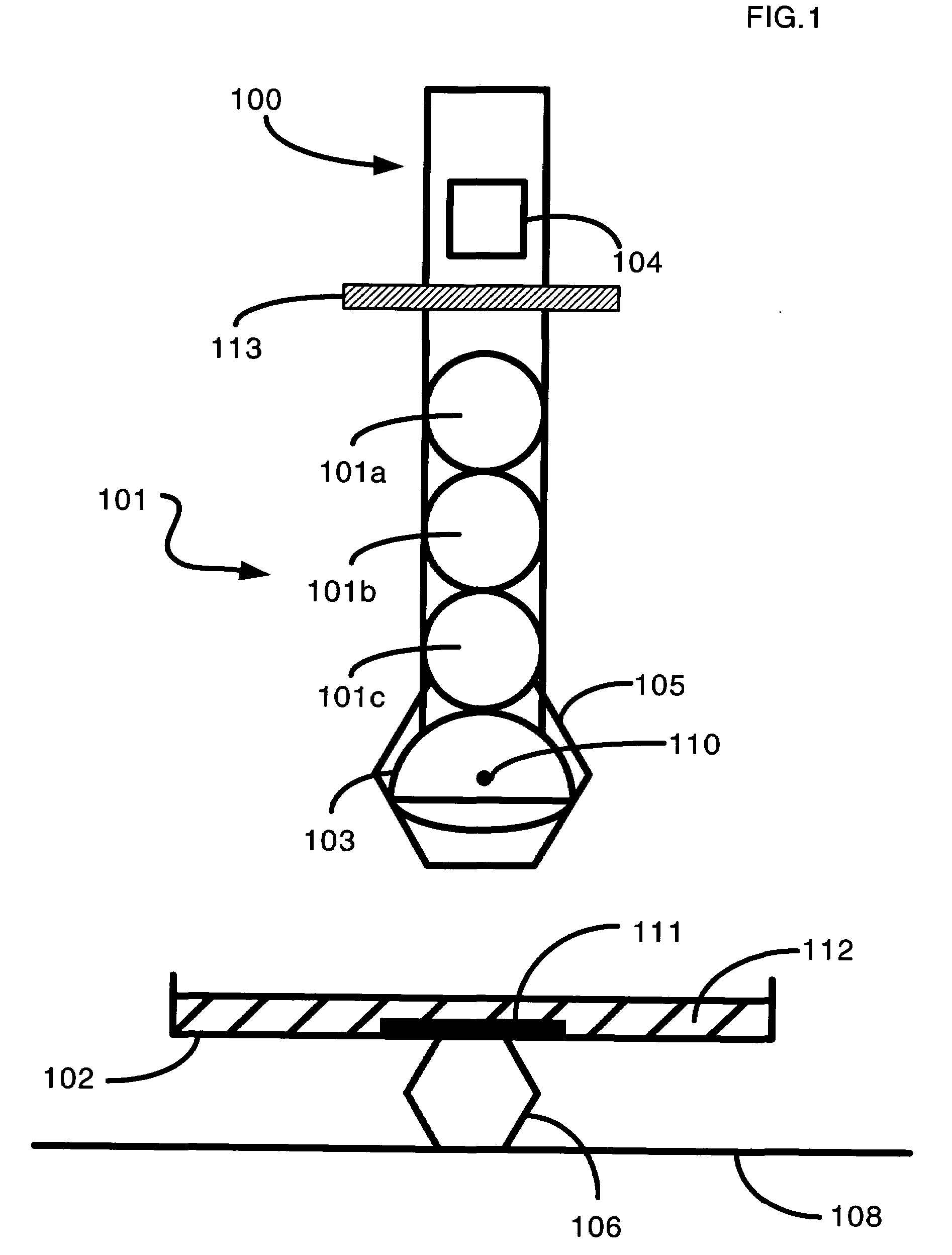
[0023]FIG. 1 is a side-view illustration of an embodiment of the overall invention. A frame 100 serves as a support structure to hold the various related components. Light source 104 is attached to frame 100 and projects the light through a photomask 113 and a lens system 101 having lens elements 101a, 101b, 101c and final lens element 103. Examples of light sources for light source 104 are excimer lasers and mercury arc lamps. Lens system 101a, 101b, 101c an...


PUM

PropertyMeasurementUnit
wavelengthaaaaaaaaaa
relative horizontal velocityaaaaaaaaaa
angular velocityaaaaaaaaaa

Abstract

An apparatus for immersion optical lithography having a lens capable of relative movement in synchrony with a horizontal motion of a semiconductor wafer in a liquid environment where the synchronous motion of the lens apparatus and semiconductor wafer advantageously reduces the turbulence and air bubbles associated with a liquid environment. The relative motions of the lens and semiconductor wafer are substantially the same as the scanning process occurs resulting in optimal image resolution with minimal air bubbles, turbulence, and disruption of the liquid environment.

Description

BACKGROUND OF THE INVENTION[0001]1. Field of the Invention[0002]The current invention generally relates to optical lithography, and more specifically relates to optical lithography implemented in an immersion liquid environment.[0003]2. Description of the Related Art[0004]The widespread utilization of computer systems to solve complex problems has created a demand for applications designed to produce solutions using increasingly complex algorithms. As the complexity of the problems has increased, so too have the computational requirements of the applications used to solve these problems. The ability of computer systems to produce accurate results in an efficient manner is determined by both the application design and computer system hardware running the application.[0005]Increases in computer hardware performance are continuously strained by design specifications that push the physical properties of the materials that comprise a computer chip. Increased demands in performance requir...

Claims


Application Information

Patent Timeline
Patent Type & Authority Patents(United States)
IPC IPC(8): G03B27/42G01J1/00G03B27/52G03B27/32G03F7/20H01L21/027
CPCG03F7/70341G03F7/70258
Inventor HAKEY, MARK CHARLESHORAK, DAVID VACLAVKOBURGER, III, CHARLES WILLIAMMITCHELL, PETER H.
Owner INT BUSINESS MASCH CORP
Why Eureka
Try Eureka