Internal combustion engine and fuel injection control device therefor

a technology for internal combustion engines and control devices, which is applied in the direction of electrical control, machines/engines, automatic ignition control, etc., can solve the problems of deteriorating fuel ignitability, shortening the total injection time of fuel injection, and affecting the effect of divided injection

Inactive Publication Date: 2006-08-15
HITACHI LTD
View PDF14 Cites 13 Cited by
  • Summary
  • Abstract
  • Description
  • Claims
  • Application Information

AI Technical Summary

Benefits of technology

[0035]In addition, it is effective that the swirl guide part is installed on the

Problems solved by technology

However, it has been understood that the fuel spray is crushed by the pressure of the combustion chamber when the fuel spray is injected to the combustion chamber where pressure was improved by the supercharging machine, the fuel distribution in the center part of the fuel spray rises (in a word, the fuel spray concentrates on a specific part), and there is a tendency that the ignitability of the fuel deteriorates in the technology described in the above-mentioned Japanese Patent Application No. 2

Method used


Image

  • Internal combustion engine and fuel injection control device therefor
  • Internal combustion engine and fuel injection control device therefor
  • Internal combustion engine and fuel injection control device therefor

Examples


Embodiment Construction

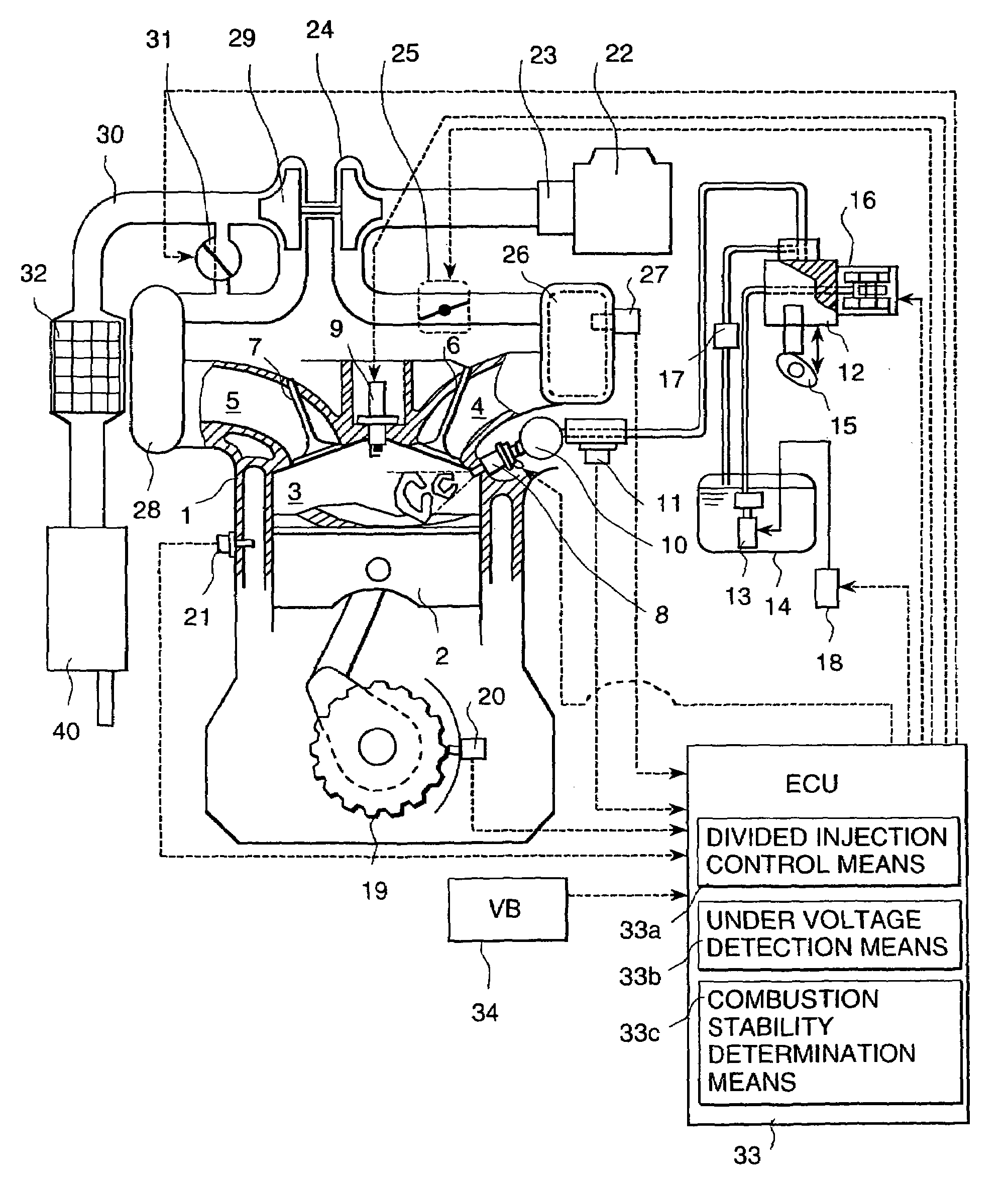
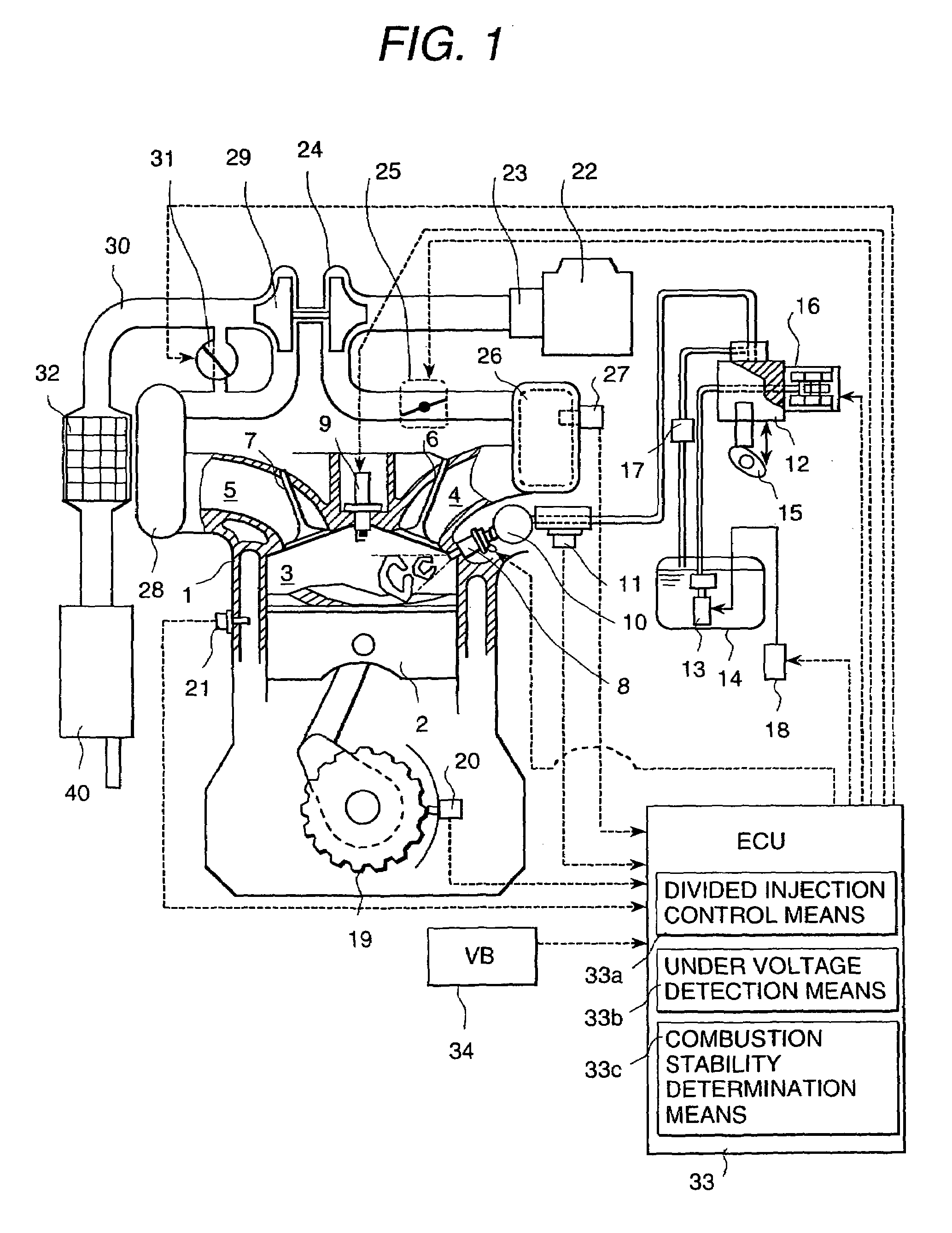
[0067]The embodiment of the present invention is explained by using the drawings. The fuel cylinder injection engine with the turbocharger according to an embodiment of the present invention is shown in FIG. 1 and FIG. 2.

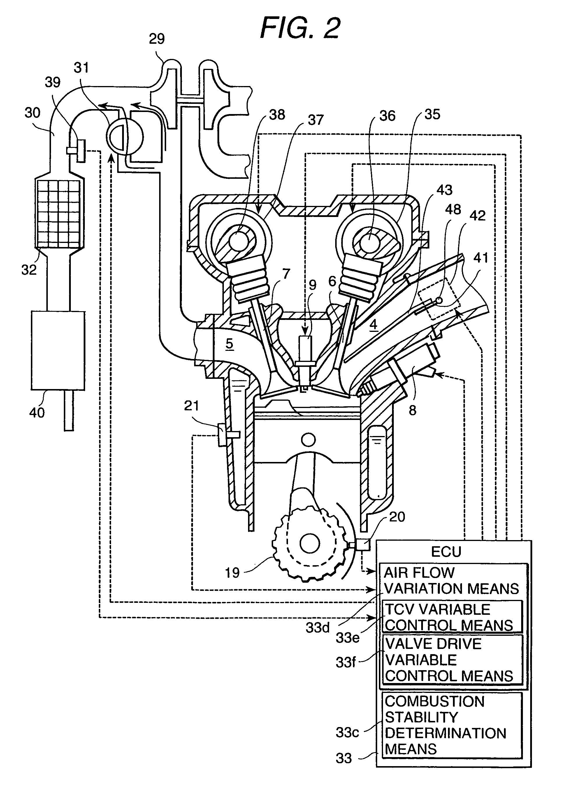
[0068]FIG. 1 shows one embodiment of the configuration of the engine. Moreover, FIG. 2 is an embodiment of a different configuration. The configuration of the entire engine is described by using FIG. 1 first.

[0069]Combustion chamber 3 is formed with a cylinder block and a cylinder head which forms engine 1, piston 2 inserted in the cylinder block, as for the fuel cylinder injection engine with the above-mentioned turbocharger, and plural cylinders are installed.

[0070]Two suction ports 4 and two exhaust ports 5 open to combustion chamber 3 which is one cylinder, and two suction valves 6 and two exhaust valves 7 which open and shut the opening is provided. Fuel injection valve 8 is installed between suction valves 6 and on the suction sidewall of combustion chamber 3,...


PUM


Abstract

In the fuel cylinder injection engine with the supercharging machine, the ignitability deteriorates because the density of the fuel at the spray center becomes excessive due to the shrinkage of the fuel spray under the supercharging. As a result, the density of the smoke and the hydrocarbon exhaust rate increase. The mixture of the fuel and the air under the supercharging is promoted by the control by TCV installed in the suction port which is a divided spray and air flow generation mechanism and the valve timing control of the suction and exhaust valve, etc.

Description

[0001]This application is a divisional of application Ser. No. 10 / 041,606, filed Jan. 10, 2002 now U.S. Pat. No. 6,748,919.BACKGROUND OF THE INVENTION[0002]The present invention relates to a fuel injection control device for an internal combustion engine. The present invention relates especially to a fuel injection control device for an internal combustion engine of a so-called fuel cylinder injection type which injects the fuel directly to the combustion chamber. More concretely, the present invention relates also to a fuel cylinder injection engine with a the supercharging machine.[0003]The fuel cylinder injection engine with the supercharging machine is disclose in the Japanese Patent Application Laid-Open No. 2000-54894. In the fuel injection control device of this prior art, the fuel spray is divided within the range of the ignition time and the intake stroke when the acceleration is detected, and the fuel injection timing in the later term is set after the middle term of the c...

Claims


Application Information

Patent Timeline
IPC IPC(8): F02M51/00B05B1/30F02P5/15F01N3/20F01N3/24F02B17/00F02B23/08F02B23/10F02B31/00F02B31/02F02B75/12F02D13/02F02D19/02F02D23/00F02D41/00F02D41/02F02D41/04F02D41/34F02D41/40F02D43/00F02D45/00F02F1/24F02F3/26F02M25/07F02M51/06F02M61/14F02M61/18F02M67/02
CPCF02B23/104F02D13/0219F02D13/0261F02D41/402Y02T10/123F02D13/0246F02D2041/001F02D2041/0015F02D2041/389F02D2250/38F02F2001/245Y02T10/125Y02T10/44Y02T10/18F02B2075/125Y02T10/12Y02T10/40
Inventor ABO, MATSUHARUTANABE, YOSHIYUKIFUJII, HIROSHIONISHI, KOJIISHII, TOSHIOFUJIEDA, MAMORU
Owner HITACHI LTD
Why Eureka
Try Eureka