Transmitter with laser monitoring and wavelength stabilization circuit

a technology of wavelength stabilization circuit and transmitter, which is applied in the field of laser diodes, can solve the problems of increasing cost and assembly complexity, close thermal coupling between laser and photodiodes, and inability to measur

Active Publication Date: 2006-08-15
LUMENTUM OPERATIONS LLC
View PDF7 Cites 47 Cited by
  • Summary
  • Abstract
  • Description
  • Claims
  • Application Information

AI Technical Summary

Benefits of technology

[0019]a memory circuit operationally coupled to the feedback circuit and the temperature sensor for storing a lookup table comprising a plurality of stored values, said stored values accounting for the light from the light source coupled to the photodetector when it is forward biased and corresponding to control voltag

Problems solved by technology

Typically these photodiodes are physically mounted very close to the laser, which results in a close thermal coupling between the laser and photodiode.
A thermistor also requires space within the housing, adds two feed-throughs to the laser package, and increases cost and assembly complexity.
Although this solution may provide some advantages, during the measurement of temperature, the light source is switched off and the measurement is not a true measurement of the device with the laser on.
Furthermore, data transmission must be halted during the time the light source is switched off; which is unacceptable in many instances.
Furthermore, the circuitry required in this embodiment is more complex and less convenient to place in a small hermetic package.
Therefore, if a forward biased photodiode i

Method used


Image

  • Transmitter with laser monitoring and wavelength stabilization circuit
  • Transmitter with laser monitoring and wavelength stabilization circuit
  • Transmitter with laser monitoring and wavelength stabilization circuit

Examples


Embodiment Construction

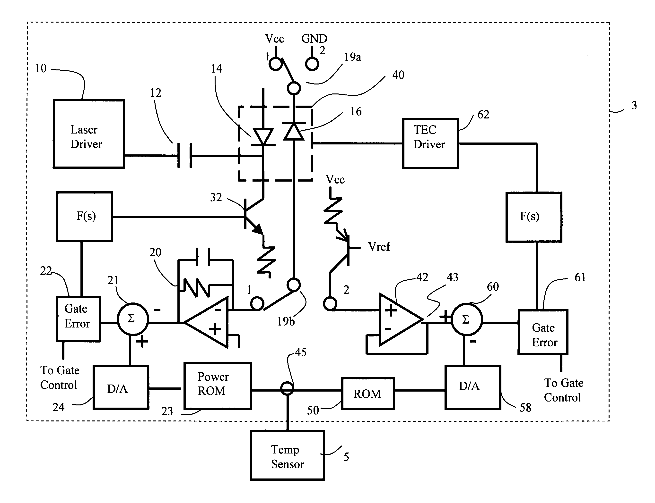
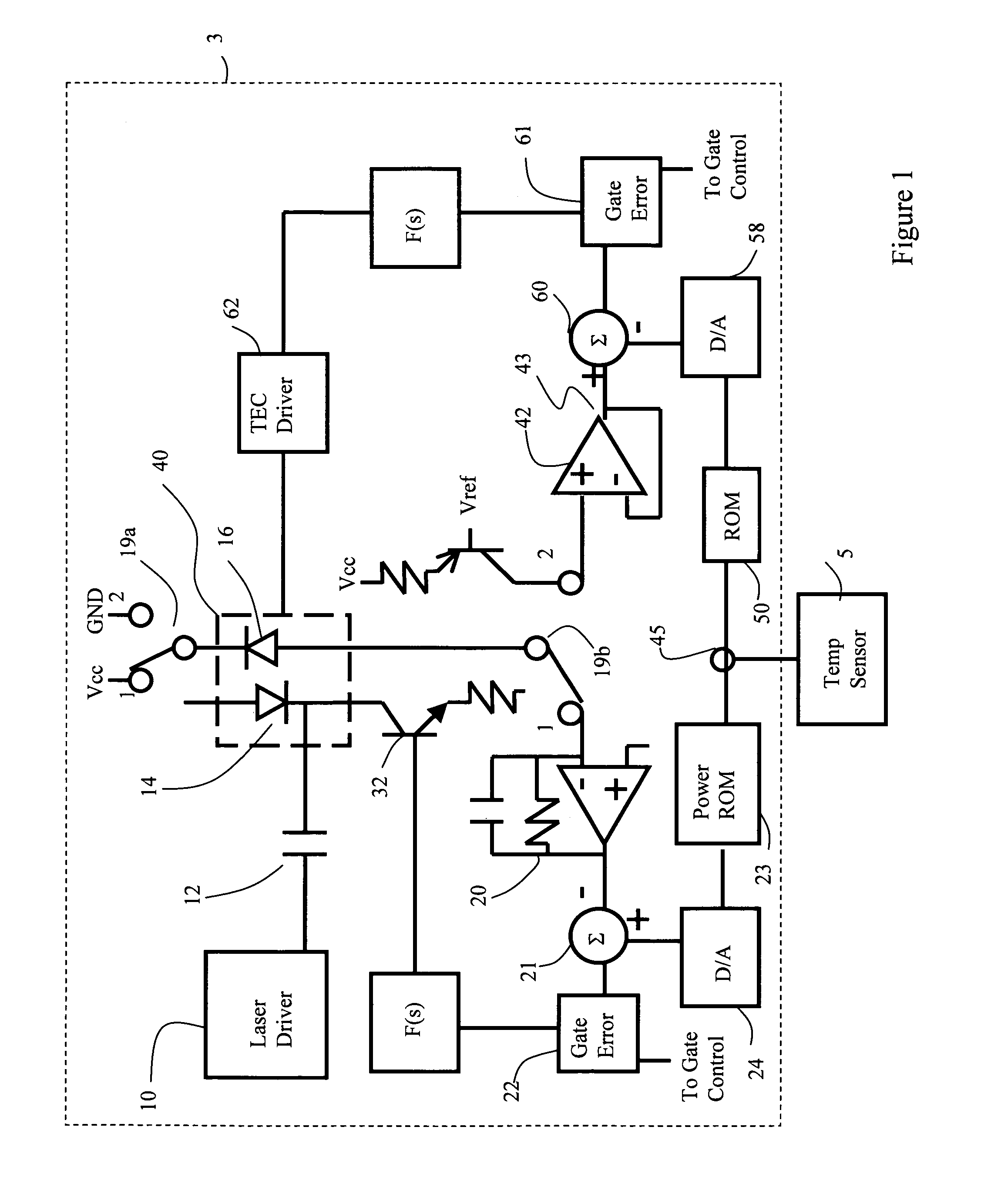
[0024]Referring now to FIG. 1, a circuit is shown for providing a diode laser output signal having substantially non-varying output power at a substantially non-varying output wavelength. All of the components described hereafter are preferably contained within a hermetically sealed package 3, with the exception of a temperature sensor 5, which is disposed outside the package 3. Alternatively, all of the electronics may be disposed outside of a hermeticallysealed portion of the package 3. An output signal from the temperature sensor 5 is electrically, coupled to components inside the hermetically sealed package 3.

[0025]A laser driver 10 is coupled through a capacitor 12 to an input terminal of a light emitting diode or laser diode 14. A photodiode or photodetector 16 is disposed close to the laser diode 14 for detecting the power of the output light therefrom, when the photodetector 16 is in a reversed biased mode of operation. In this mode of operation the photodetector 16 serves a...


PUM


Abstract

An optical monitoring circuit includes a photoelectric device such as a photo-detector that produces a signal in response to incident light thereon corresponding to a characteristic of the incident light such as intensity, or wavelength. A light source is disposed within the circuit for emitting a beam of light, a portion of which is to be incident upon the photoelectric device. The photoelectric device when reversed biased provides an output electrical signal from which the intensity of light from the light source impinging thereon can be determined. The photoelectric device when forward biased provides an output signal from which the temperature of the photoelectric device can be determined. A method and circuit are disclosed for calibrating out the unwanted effect of light from the light source affecting accuracy of the determined temperature derived from the output signal when the photoelectric device is forward biased.

Description

CROSS REFERENCE TO RELATED APPLICATION[0001]This application claims priority of U.S. Provisional Patent Application No. 60 / 405,736 filed Aug. 26, 2002, entitled “Method For Laser Temperature Measurement With Monitor Photodiode”, which is incorporated herein by reference for all purposes.FIELD OF THE INVENTION[0002]This invention relates to a laser diode within a package having an output signal with a non-varying output wavelength as temperature outside the laser package varies.BACKGROUND OF THE INVENTION[0003]A communications laser is frequently placed in a hermetic package that includes a photodiode optically coupled to the laser diode. The photodiode forms part of a feedback circuit, which samples a portion of the laser light to produce a photocurrent used to control the bias current of the laser in order to stabilize the light output power thereof. Typically these photodiodes are physically mounted very close to the laser, which results in a close thermal coupling between the las...

Claims


Application Information

Patent Timeline
IPC IPC(8): G01J1/32H01S3/04H01S3/10G01J1/44
CPCG01J1/44
Inventor WILSON, ARTHUR G.SLAPO, JR., DAVIDWERNLUND, JAMES V.
Owner LUMENTUM OPERATIONS LLC
Why Eureka
Try Eureka