Method and apparatus for crystal analysis

a crystal analysis and crystal technology, applied in the field of crystal analysis and crystal analysis apparatus, can solve the problems of difficult to have the resolution (ie., spatial resolution power) raised higher than the existing value, and the correlation between the two can not be easily identified, so as to achieve the effect of high resolution and eas

Inactive Publication Date: 2006-08-15
TDK CORPARATION
View PDF11 Cites 5 Cited by
  • Summary
  • Abstract
  • Description
  • Claims
  • Application Information

AI Technical Summary

Benefits of technology

[0011]It is an object of the present invention to provide a method of crystal analysis capable of measuring the crystallographic orientations and crystal systems of crystal grains on a specimen surface with high resolution and with ease.
[0012]It is another object of the present invention to provide an apparatus for crystal analysis capable of measuring the crystallographic orientations and crystal systems of crystal grains on a specimen surface with high resolution and with ease.
[0019]The present invention observes the amount of the secondary electrons when irradiating the surface of a specimen with an ion beam, follows up the variation in the amount of the second electrons when the angle of incidence of the ion beam with respect to the specimen varies, and identifies the crystallographic orientation and crystal system on the specimen. While the equivalent measurement results can be obtained by means of the EBSP method as well which irradiates with an electron beam, the ion beam irradiation at a small angle of incidence, i.e., in the angular direction nearer the normal line of the surface of the specimen according to the present invention allows easy comparison of the observed microscopic images with the identified results of the crystallographic orientations. Furthermore, in the EBSP method, it is basically difficult to enhance the resolution, because a diffraction beam created by means of the Bragg diffraction is employed. In contrast, because the present invention is based on the channeling phenomenon of ions, which are particles, an improvement of the resolution is easy, and it is enabled to determine the crystallographic orientations of finer crystal grains. While the resolution achieved by the EBSP method is the order of several tens of nanometers, it is enabled according to the present invention easily to obtain the resolution of several nanometers and if the diameter of the focused ion beam is made thinner, further enhancement of the resolution can be attained.

Problems solved by technology

However, a problem has been that, because, in the EBSP method, the electron beam impinges on a specimen surface at a large angle of incidence, minute unevennesses of the surface affect on the result of the analysis and the correspondence between the distribution of the crystallographic orientations observed through the EBSP method and the microscopic image observed through the ordinary scanning microscopic photographs cannot easily be identified.
Furthermore, because the diffraction pattern is caused by the Bragg reflection from crystal grains, it is basically difficult to have the resolution (ie., spatial resolving power) raised higher than the existing value, practically the resolution being of the order of several tens of nanometers.
While a crystal system and a crystallographic orientation can be decided by the X-ray diffraction method as well, it is difficult in the case of the X-ray to narrow the beam and consequently the resolution is of the order of ten micrometers.
Furthermore, the penetration depth of the X-ray is so deep that it is difficult to decide the crystallographic orientation in the outermost surface of a specimen.
This method, however, is problematic in that the measuring devices to be employed tend to be complicated, such as a two-dimensional ion detector, a parallel magnetic field generator and the like and in addition, a long measurement time tends to be required for measuring the two-dimensional distribution of the scattered ions.
The EBSP method, however, is problematic in that because the electron beam impinges on a specimen surface at a large angle of incidence, minute unevennesses of the surface affect on the result of the analysis, and that the resolution is of the order of tens of nanometers.
While alternatively to the EBSP method, there exist methods of analyzing and identifying the crystal systems and crystallographic orientations of fine crystal grains on a specimen surface, such methods are not necessarily practical as compared to the EBSP method.

Method used


Image

  • Method and apparatus for crystal analysis
  • Method and apparatus for crystal analysis
  • Method and apparatus for crystal analysis

Examples


Embodiment Construction

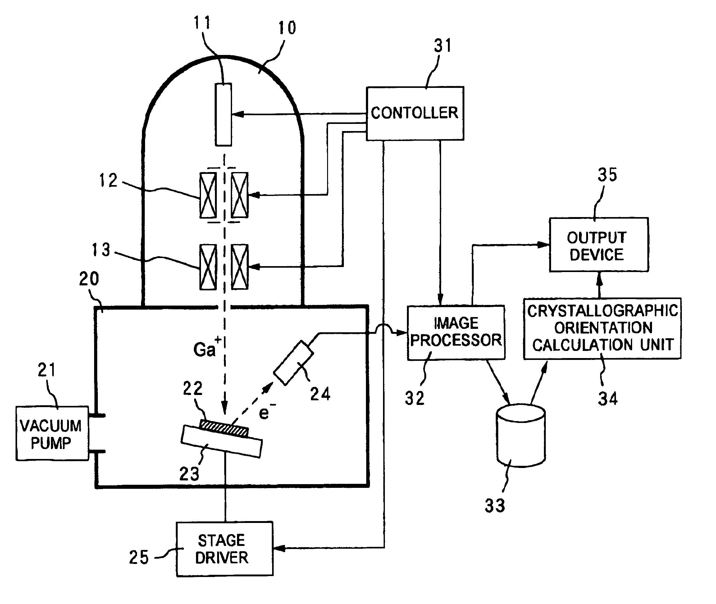
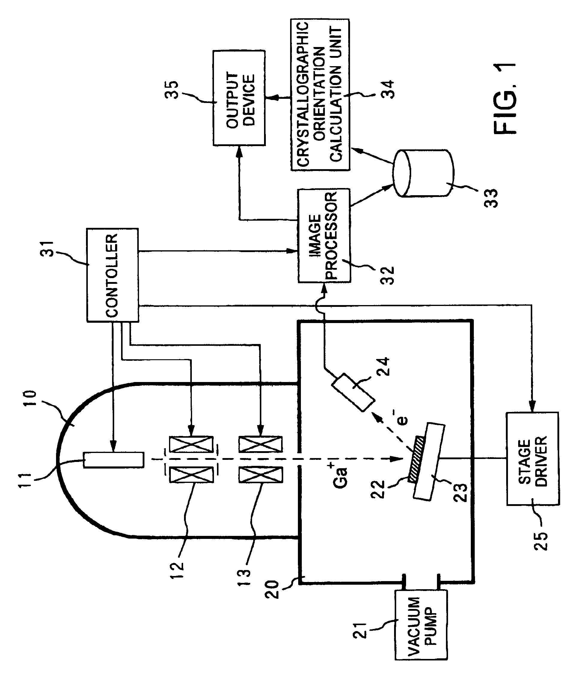
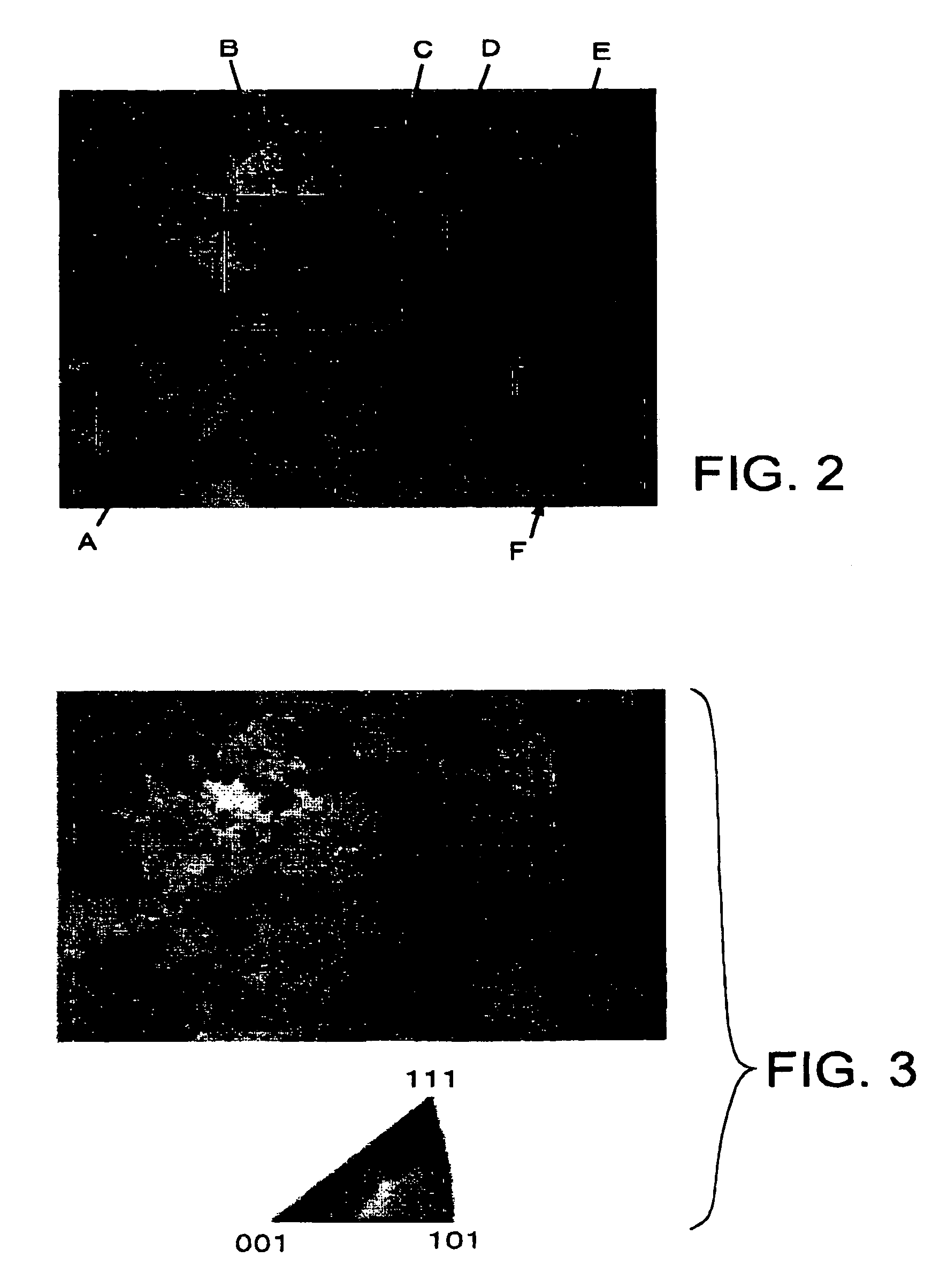
[0026]The method of crystal analysis according to the present invention is intended for analyzing the crystallographic orientations and crystal systems of a specimen surface based on the relation between the intensity of the secondary electron emitted from the specimen when the specimen surface is irradiated with an ion beam and the angle of incidence of the ion beam impinging on the specimen. It is possible to obtain the data that represent a two-dimensional distribution of the crystallographic orientations of crystal grains on a specimen surface by performing an observation by means of the scanning ion microscope while varying the incidence angle of the ion beam with respect to a specimen surface and analyzing a plurality of the scanning ion microscope images (hereinafter referred to as the SIM images) acquired at different incidence angles. This data representative of the two-dimensional distribution is equivalent to an inversion pole figure obtained by the measurements according...


PUM

PropertyMeasurementUnit
inclination angleaaaaaaaaaa
acceleration voltageaaaaaaaaaa

Abstract

The method of measuring crystallographic orientations, crystal systems or the like of the surface of a specimen has steps of: irradiating the specimen with an ion beam; measuring the secondary electrons generated by the irradiation of the ion beam; repeating the irradiation of the ion beam and the measurement of the secondary electrons with each variation in an angle of incidence of the ion beam with respect to the specimen; and determining the crystalline state based on the variation in the amount of the secondary electrons corresponding to the variation of the angle of incidence.

Description

BACKGROUND OF THE INVENTION[0001]1. Field of the Invention[0002]The present invention relates to a method of crystal analysis and an apparatus for crystal analysis capable of analyzing crystalline states such as the crystallographic orientations of individual crystal grains on the surface of a specimen.[0003]2. Description of the Related Arts[0004]The recent development of micromachining technologies has come to require the technologies for analyzing crystal system and crystallographic orientations of crystal grains on a solid surface or the like. For example, a fine copper (Cu) wiring formed by a plating process has been employed for a coil wiring of a write element for a magnetic head employed in a hard-disk drive. In this copper wiring, the orientations of microcrystals and the structures of crystal-grain boundaries make a difference in a resistance value of the wire, causing variations in the characteristics of the magnetic head. For this reason, control of crystal growth has be...

Claims


Application Information

Patent Timeline
Patent Type & Authority Patents(United States)
IPC IPC(8): H01J37/252G01N23/207G01N23/225H01J49/46H01J37/20H01J37/22H01J37/244H01J37/256
CPCG01N23/225H01J37/256H01J2237/2527
Inventor YANAGIUCHI, KATSUAKIOKAWA, WAKAKO
Owner TDK CORPARATION
Why Eureka
Try Eureka