
Controlled power source for underground line location

a technology of power source and underground line, applied in the direction of electric controller, ignition automatic control, instruments, etc., can solve the problem of emitted magnetic field from underground line, and achieve the effect of constant current and minimized impedance of underground lin

Inactive Publication Date: 2006-08-15
BUSAN TRANSPORTATION CORPORATION
View PDF12 Cites 78 Cited by
  • Summary
  • Abstract
  • Description
  • Claims
  • Application Information

AI Technical Summary

Benefits of technology

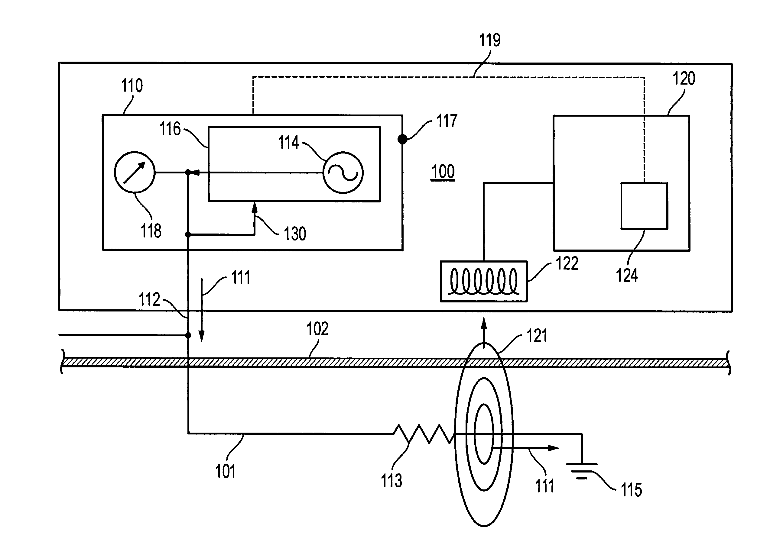
[0010]In accordance with the present invention, a transmitter for an underground line locator system which provides a constant output to the underground line is presented. The effects of the impedance of the underground line, therefore, is minimized. In some embodiments, the electrical power, current or voltage output of the transmitter can also be controlled. A transmitter according to the present invention includes a source that produces a substantially constant current when coupled to an underground line for a range of impedances of the underground line. In some embodiments, once an upper limit of voltage or power is reached, the voltage or power is held constant by the source instead of the current.
[0012]In some embodiments, the transmitter monitors the current and voltage of the output and adjusts the voltage to provide a constant current essentially independent of the resistance of the line. In some embodiments, the transmitter holds the voltage to within preset limits of voltage or so as to fall within a range of power. Preset limits of power and voltage may be set by a user of the line locator system, or may be preset in the line-locator system. If the resistance of the line is such that the voltage required to achieve the desired current exceeds the preset limit, then the transmitter changes from constant current output to constant voltage output, and the current is allowed to decrease as required to maintain the maximum voltage. If the resistance of the line is such that the power output of the transmitter exceeds a preset limit, then the voltage is decreased such that the power does not exceed its limit. These embodiments allow operation of the transmitter as a constant-current source and additionally limit the maximum voltage that will be applied to the underground line, so that the line will not be damaged, or limit the maximum power applied to the line, to insure compliance with the regulations of the Federal Communications Commission or other regulatory body.

Problems solved by technology

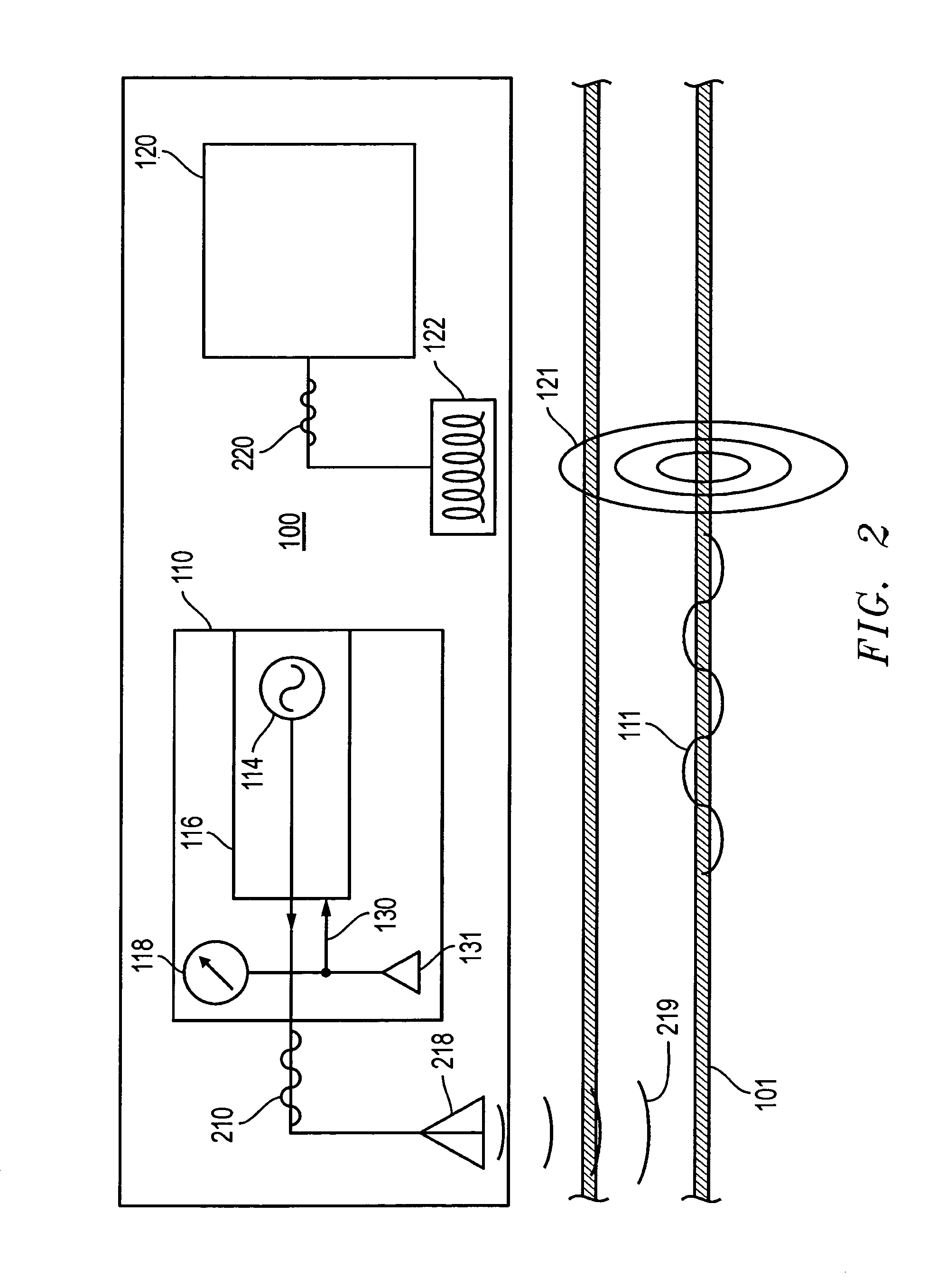
The transmitter can be electrically coupled to the underground line to be located to cause an electric current to flow in that underground line, which results in the emission of a magnetic field from that line.

Method used


Image

  • Controlled power source for underground line location
  • Controlled power source for underground line location
  • Controlled power source for underground line location

Examples


Embodiment Construction

[0022]There is a significant improvement in line location utilizing a transmitter according to the present invention, which results in a constant and known generated magnetic signal from the underground line for a broad range of impedance of that line. Since the current, and not the power or voltage, in the underground line determines the strength of the generated magnetic field, and therefore the success and accuracy with which the line can be located, generating a constant current is an efficient and effective way of energizing an underground line in order to facilitate its location by a receiver of a line locator system. Using more current than is necessary results in reducing the life of the battery that powers the transmitter. Using too little current reduces the performance of the receiver and its ability to accurately locate the underground line.

[0023]In some embodiments, the voltage applied to the target underground line is also controlled so as not to damage the line or equ...


PUM


Abstract

A transmitter for a line locator system that controls the electrical current, voltage or power applied to the target line is disclosed. Control of the electrical output of the transmitter can be achieved passively or by means of a feedback control system. A transmitter connected directly to a line can include an operator control and monitoring of current being supplied to a line to be located. Some transmitters include a current regulating circuit that controls current supplied to a line. In some transmitters, feedback controllers and feedback loops are used to regulate output current, voltage or power. Some control loops are based on monitoring currents in circuits; some control loops monitor power output from an inductive mode transmitter antenna. An inductively coupled transmitter with power output control is also disclosed.

Description

BACKGROUND[0001]1. Field of the Invention[0002]This invention relates to the field of underground line location systems and, in particular, to devices for electrically coupling power to concealed objects so that they can be located by an underground line locator.[0003]2. Related Art[0004]Underground line locators are used to locate the position of lines buried in the ground (i.e., underground lines) such as gas pipes, water pipes, telephone cables, and power cables. A line locator system typically includes a transmitter and a receiver. The transmitter can be electrically coupled to the underground line to be located to cause an electric current to flow in that underground line, which results in the emission of a magnetic field from that line. The receiver locates the underground line by detecting the radiated magnetic field from the underground line.[0005]In a direct connection mode, the transmitter is conductively coupled to the line to be located, typically at a point in the line ...

Claims


Application Information

Patent Timeline
IPC IPC(8): G08B21/00
CPCG01V3/081H02G9/02H02G9/00
Inventor BIGELOW, RUSSELL N.POLAK, STEVANLONG, JAMESSHTARGOT, JOSEPH
Owner BUSAN TRANSPORTATION CORPORATION
Learn More