
Force feedback device including non-rigid coupling

Inactive Publication Date: 2006-08-15
IMMERSION CORPORATION
View PDF286 Cites 26 Cited by
  • Summary
  • Abstract
  • Description
  • Claims
  • Application Information

AI Technical Summary

Benefits of technology

[0010]The present invention provides a human / computer interface apparatus and method which can provide multiple degrees of freedom and highly realistic force feedback to a user of the apparatus. The preferred apparatus includes a local microprocessor used for enabling feel sensations including virtual walls and viscous damping in a virtual environment, thus permitting a low-cost force feedback interface device to be implemented.
[0014]The interface of the present invention enables force sensations in a virtual environment, such as hard walls and viscous damping, advantageously using a low cost interface device. A local microprocessor receives commands from the host computer, decodes the commands, outputs actuator signals in accordance with the commands, receives sensor signals, and reports data to the host in response to the commands, thus relieving the host computer of substantial computational burden and allowing a slower interface between host and interface device to be used. Viscous damping is enabled using the local microprocessor to compute present and previous positions of the user manipulated object to determine an amount of viscous force. Virtual walls are likewise enabled by using the microprocessor to track positions of the user object to determine when wall forces are output. These improvements allow a computer system to accurately control a low-cost interface providing realistic force feedback.

Problems solved by technology

This configuration has disadvantages in the inexpensive mass market, since the functions of reading sensor data and outputting force values to actuators can be a burden on the host computer's processor which detracts from the performance of the host in other host tasks and application execution.
In addition, low bandwidth interfaces are often used, which reduces the ability of the host computer to control realistic forces requiring high frequency signals.
However, the system described by Kramer includes a host computer directly controlling the actuators of the device, and thus has the disadvantages mentioned above.
In addition, the Kramer device is not easily applicable to simulated environments where an object is referenced in virtual space and force feedback is applied to the object.
In addition, the exoskeleton devices of Kramer can be complex, cumbersome or even dangerous to the user if extensive devices are worn over the user's appendages.
Since actuators which supply force feedback tend to be heavier and larger than sensors, they would provide inertial constraints if added to a device.
There is also the problem of coupled actuators, where each actuator is coupled to a previous actuator in a chain such that a user who manipulates the object must carry the inertia of all of the subsequent actuators and links except for the first actuator in the chain.
These types of interfaces also introduce tactile “noise” to the user through friction and compliance in signal transmission and limit the degree of sensitivity conveyed to the user through the actuators of the device.
While active actuators often provide quite realistic force feedback, they can also be quite bulky and typically require large power supplies to operate.
In many situations, such high speed control signals and high power drive signals are not available or too costly, especially in the competitive, low-cost market of personal computers.
Furthermore, active actuators can sometimes prove unsafe for a user when strong, unexpected forces are generated on a user of the interface who does not expect those forces.

Method used


Image

  • Force feedback device including non-rigid coupling
  • Force feedback device including non-rigid coupling
  • Force feedback device including non-rigid coupling

Examples


Embodiment Construction

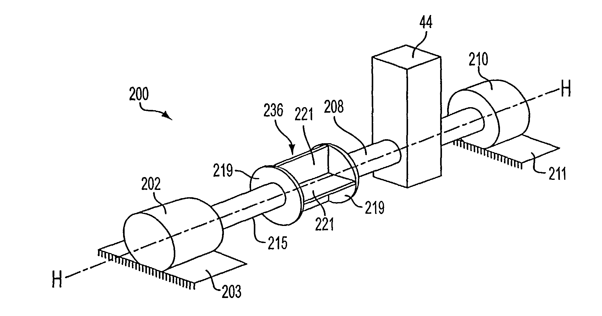
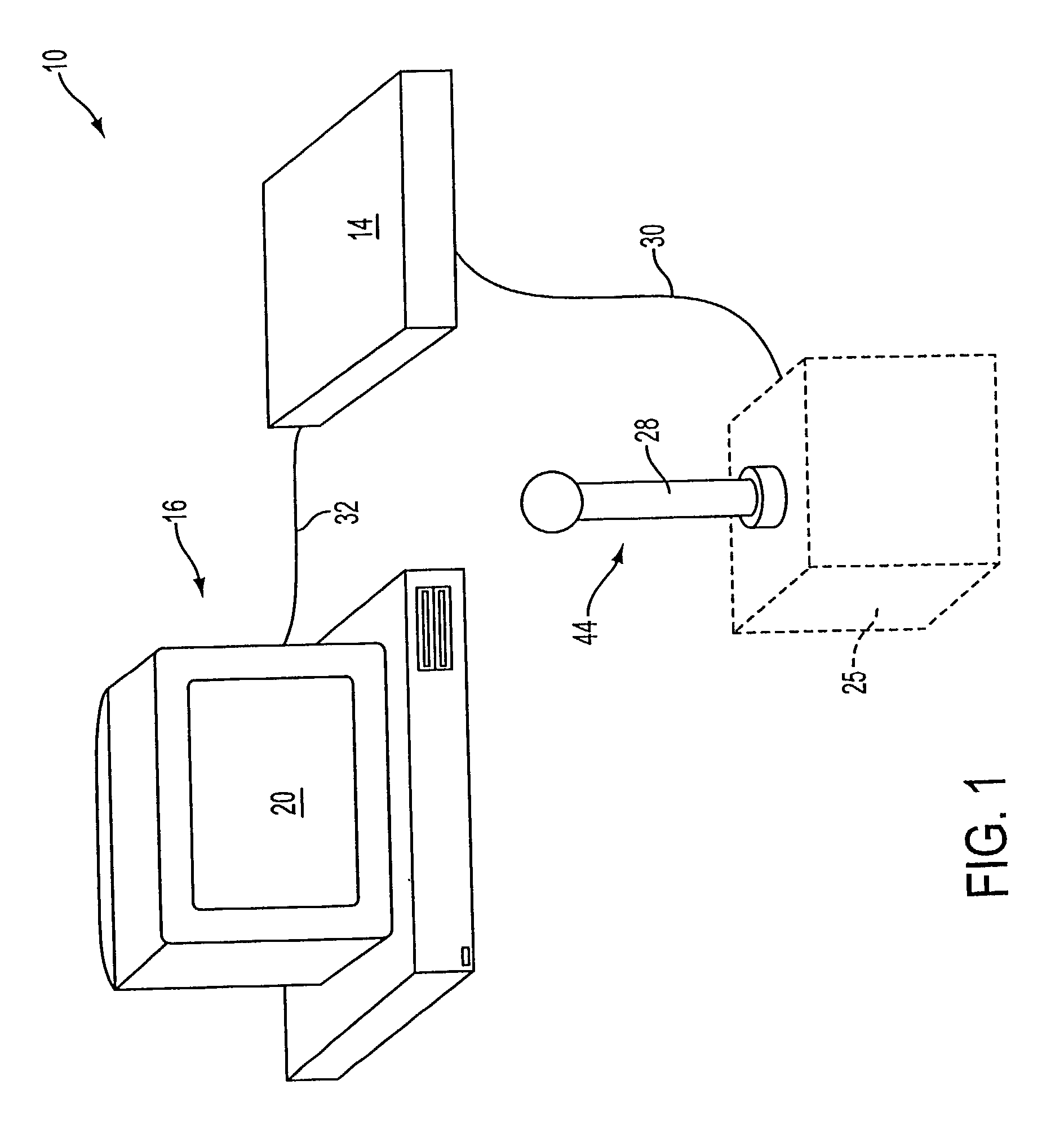
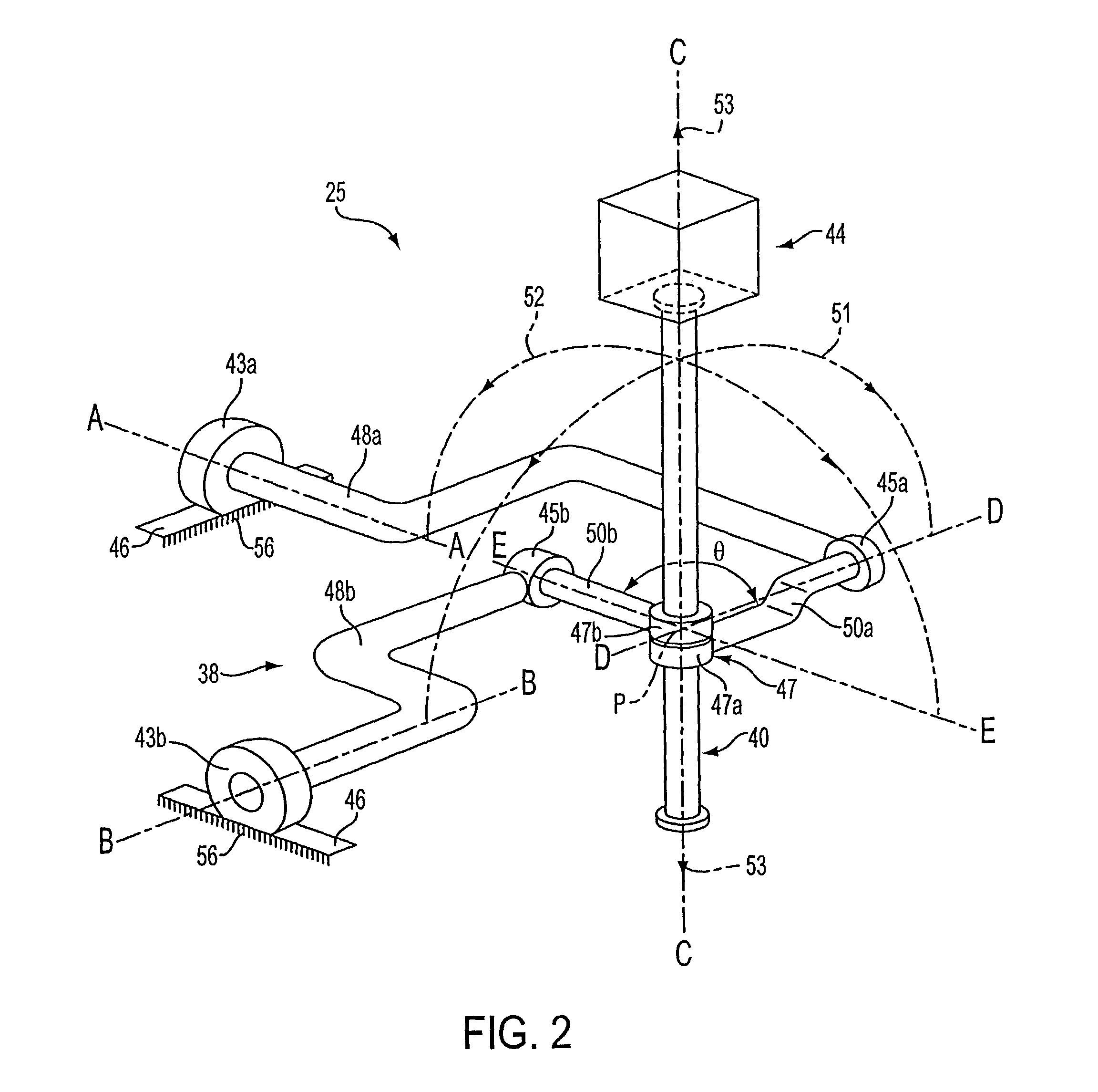
[0046]In FIG. 1, a force feedback system 10 includes a human / computer interface apparatus 12, an electronic interface 14, and a host computer 16. The illustrated system 10 can used for a virtual reality simulation, video game, training procedure or simulation, use of a computer application program, or other application. In one preferred embodiment, a user manipulatable object 44 is grasped by a user and manipulated. Images are displayed on a display apparatus, such as screen 20, of the computer 16 in response to such manipulations.

[0047]The computer 16 is a preferably a personal computer or workstation, such as an IBM-PC compatible computer, Macintosh personal computer, or a SUN or Silicon Graphics workstation. Most commonly, the digital processing system is a personal computer which operates under the Windows™, Unix, MacOS, or similar operating system and may include a host microprocessor such as a Pentium, PowerPC, or other type of microprocessor.

[0048]The software running on the ...


PUM


Abstract

A method and apparatus for providing force sensations in virtual environments includes a human / computer interface device and method used in conjunction with a host computer and which can provide feel sensations to a user of the device. A user manipulatable object physically contacted by a user, such as a joystick, stylus, pool cue, or other object, is movable in multiple degrees of freedom using a gimbal mechanism. A local microprocessor, separate from the host computer, enables communication with the host computer and receives commands from the host, decodes the commands, outputs actuator signals in accordance with commands, receives sensor signals, and reports data to the host in response to commands. Actuators generate feel sensations by providing a force on the user object in response to actuator signals from the local microprocessor, and sensors detect the motion of the user object and reports sensor signals to the local microprocessor. Memory is included locally to the local microprocessor for storing program instructions and routines enabling feel sensations and host-microprocessor communication. The feel sensation generated on the user is, in one embodiment, a damping sensation simulating a feel of motion through a fluid. In another embodiment, the feel sensation is a wall sensation simulating the feel of impacting a surface or obstruction.

Description

CROSS REFERENCE TO RELATED APPLICATIONS[0001]This application is a continuation of application Ser. No. 09 / 532,288, filed Mar. 22, 2000 which issued as U.S. Pat. No. 6,437,771; which is a continuation of application Ser. No. 08 / 784,803 filed Jan. 16, 1997 and which is issued as U.S. Pat. No. 6,057,828; which is a continuation-in-part of application Ser. No. 08 / 374,288, filed Jan. 18, 1995 and which issued as U.S. Pat. No. 5,731,804; and a continuation-in-part of application Ser. No. 08 / 400,233, filed Mar. 3, 1995 and which issued as U.S. Pat. No. 5,767,839; and a continuation-in-part of application Ser. No. 08 / 583,032, filed Feb. 16, 1996, and which issued as U.S. Pat. No. 5,701,140; which was the National Stage of International Application No. PCT / US94 / 07851, filed Jul. 12, 1994; which is a continuation of application Ser. No. 08 / 092,974, filed Jul. 16, 1993, abandoned.BACKGROUND OF THE INVENTION[0002]The present invention relates generally to interface devices between humans and c...

Claims


Application Information

Patent Timeline
IPC IPC(8): G09G5/08A61B19/00G01B5/008G01B21/04G05G9/047G06F3/00G06F3/01G06F3/038G09B9/28G09B23/28
CPCG09B23/28G01B5/008G01B21/04G05G9/047G06F3/011G06F3/016G06F3/0346G06F3/03545G06F3/038G06F3/0383G09B9/28A63F13/06A61B19/26A63F2300/1037A63F2300/1043A63F2300/8017G05G9/04737G05G2009/0474G05G2009/04766G06F2203/015A61B90/50A63F13/245A63F13/285A63F2300/1062A63F13/803
Inventor ROSENBERG, LOUIS B.JACKSON, BERNARD G.
Owner IMMERSION CORPORATION
Learn More