Electro optical microwave communications system

a microwave communication and optical technology, applied in electromagnetic transmission, electrical equipment, transmission, etc., can solve the problems of difficult and expensive building of radio frequency circuitry for these frequency ranges

Active Publication Date: 2006-08-15
ROCKWELL COLLINS INC
View PDF10 Cites 55 Cited by
  • Summary
  • Abstract
  • Description
  • Claims
  • Application Information

AI Technical Summary

Benefits of technology

[0015]It is an advantage of the present invention to utilize lasers and low-loss fiber optic components to aid in implementing a terahertz communications system.
[0016]It is an advantage of the present invention to provide continuous-tuning in the terahertz frequency band.
[0017]It is a feature of the present to be able to locate terahertz converters and other RF components at large distances from the remainder of the communications system due to the use of low-loss fiber optic cables.
[0018]It is a feature of the present invention to replace tunable frequency synthesizers for the terahertz range that are difficult or impossible to implement.

Problems solved by technology

Building radio frequency (RF) circuitry for these frequency ranges is very difficult and expensive and in particular a unique system must be built for each sub-band.
Government surveillance systems are already vitally concerned with signal activity in this range and are hampered by the lack of RF technology to prosecute such signals.
What is lacking is the technology to implement a continuous-tuning communications or surveillance system that covers the 20–500 GHz band, similar to the common availability today of receivers that cover 20–520 megahertz (MHz).

Method used


Image

  • Electro optical microwave communications system
  • Electro optical microwave communications system
  • Electro optical microwave communications system

Examples


Embodiment Construction

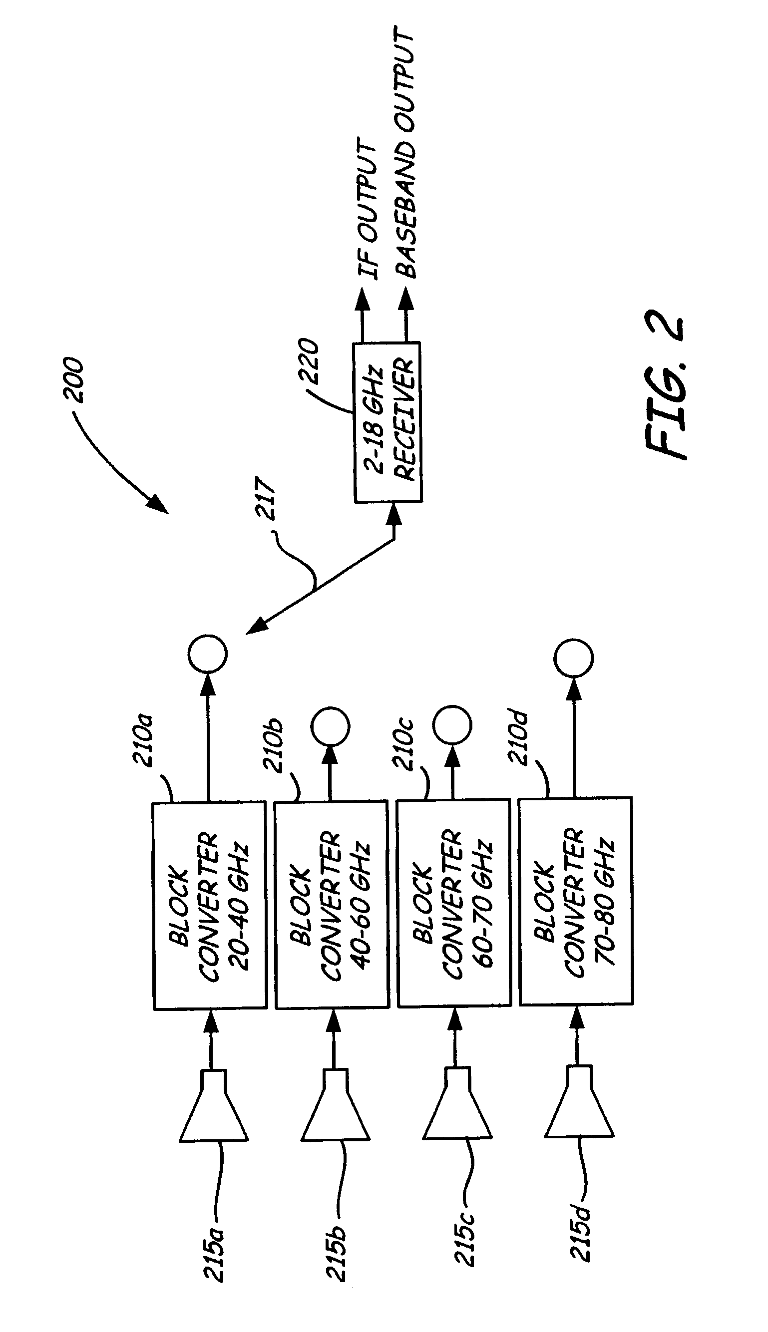
[0027]The implementation of a conventional receiver 200 for the terahertz frequency range is following the current architecture of millimeter wave receivers, that is, a group of narrowband block converters 210a–d in parallel as shown in FIG. 2. Due to component technologies, primarily the limited frequency response of each semiconductor process or structure, only a 10–20 GHz bandwidth is typically attainable. Tunable frequency synthesizers spanning any significant frequency range are difficult or impossible to implement to support a superheterodyne converter architecture. Thus a typical surveillance system consists of a bank of individual block converters 210a–d, each spanning 10–20 GHz using a fixed local oscillator (not shown), and typically each with its own antenna 215a–d to eliminate a high-loss microwave switching subsystem. These block converters 210a–d typically convert down to a 2–20 GHz range and are selected by a switch 217. A tunable receiver 220 processes and / or demodul...


PUM


Abstract

A wideband communications system uses a photomixer, a radio frequency (RF) mixer, and an antenna. The photomixer is comprised of high speed phototransistors that are illuminated by two laser beams. The laser beams are generated by two lasers, one tunable, and conveyed to the photomixer via fiber optic cables. The two beams are mixed by the photomixer to generate a radio heterodyne signal that is mixed with antenna signals to generate an intermediate frequency (IF) signal based on the differences of the generated heterodyne frequency and the antenna signals. Conventional fiber optic means may be used to convey the IF signals, along with the fiber optic cables to the photomixer, to and from a remote RF head located at some distance from the rest of the communications system to overcome losses in transmission lines.

Description

BACKGROUND OF THE INVENTION[0001]This invention relates to communications systems, microwave communications systems, and specifically an electro optic microwave communications system.[0002]As the information age has grown, the availability of wireless bandwidth has been seriously constrained by available spectrum. The obvious growth path, as spectrum becomes fully occupied or oversubscribed, is to move upward in frequency to unused bandwidth. The upper frequency limit has steadily risen to where the use of the millimeter and terahertz (THz) spectrum is now realistic. Building radio frequency (RF) circuitry for these frequency ranges is very difficult and expensive and in particular a unique system must be built for each sub-band. No known technology exists for generation (transmit) and reception (receive) of signals across multiple sub-bands or indeed across the entire band (up to 1 THz). Various absorption holes exist in the THz frequency range and hence useful communications is po...

Claims


Application Information

Patent Timeline
Patent Type & Authority Patents(United States)
IPC IPC(8): H04B10/142H04B10/145H04B10/148
CPCH04B10/25759
Inventor STERNOWSKI, ROBERT H.
Owner ROCKWELL COLLINS INC
Why Eureka
Try Eureka