
Exhaust system and method of thermal management

a technology of exhaust system and thermal management, applied in the direction of machines/engines, mechanical equipment, separation processes, etc., can solve the problems of poor engine performance, poor fuel economy, and clogging of exhaust flow with particulate matter,

Inactive Publication Date: 2006-08-22
DELPHI TECH INC
View PDF61 Cites 74 Cited by
  • Summary
  • Abstract
  • Description
  • Claims
  • Application Information

AI Technical Summary

Benefits of technology

The patent describes exhaust systems and methods for reducing NOx emissions from gas streams. The systems include a NOx adsorber, a reformer, a particulate filter, and a second oxidation catalyst. The method involves generating a gas stream with NOx and particulate, passing it through the particulate filter and NOx adsorber, and then regenerating the particulate filter and NOx adsorber. The regeneration process involves introducing a fluid with thermal energy, hydrogen, and carbon monoxide to the gas stream, heating it up, and then introducing it to the particulate filter and NOx adsorber to reduce the temperature of the gas stream. The system can also include a phosphate trap and a second oxidation catalyst to further reduce NOx emissions. The technical effect of the patent is to provide a more effective method for reducing NOx emissions from gas streams.

Problems solved by technology

A problem with diesel particulate filters is that they gradually become clogged with particulate matter impeding exhaust flow.
This excessive backpressure results in poor engine performance and poor fuel economy.
However, many passenger diesel vehicles are operated for protracted periods of time at, or close to, idling speed.
However passive diesel systems regenerate particulate traps, but do little for NOx reduction.
However, particulate oxides cannot pass through the particulate trap.
Stricter emission standards make particulate trap cleaning during the useful life of a vehicle undesirable if not unacceptable.
Eventually particulate traps cannot be regenerated because the glass layer cannot be vaporized.

Method used


Image

  • Exhaust system and method of thermal management
  • Exhaust system and method of thermal management
  • Exhaust system and method of thermal management

Examples


Embodiment Construction

[0017]It is noted that the terms “first,”“second,” and the like, herein do not denote any quantity, order, or importance, but rather are used to distinguish one element from another, and the terms “a” and “an” herein do not denote a limitation of quantity, but rather denote the presence of at least one of the referenced item. Additionally, all ranges disclosed herein are inclusive and combinable (e.g., the ranges of “up to about 25 wt %, with about 5 wt % to about 20 wt % desired,” are inclusive of the endpoints and all intermediate values of the ranges of “about 5 wt % to about 25 wt %,” etc.).

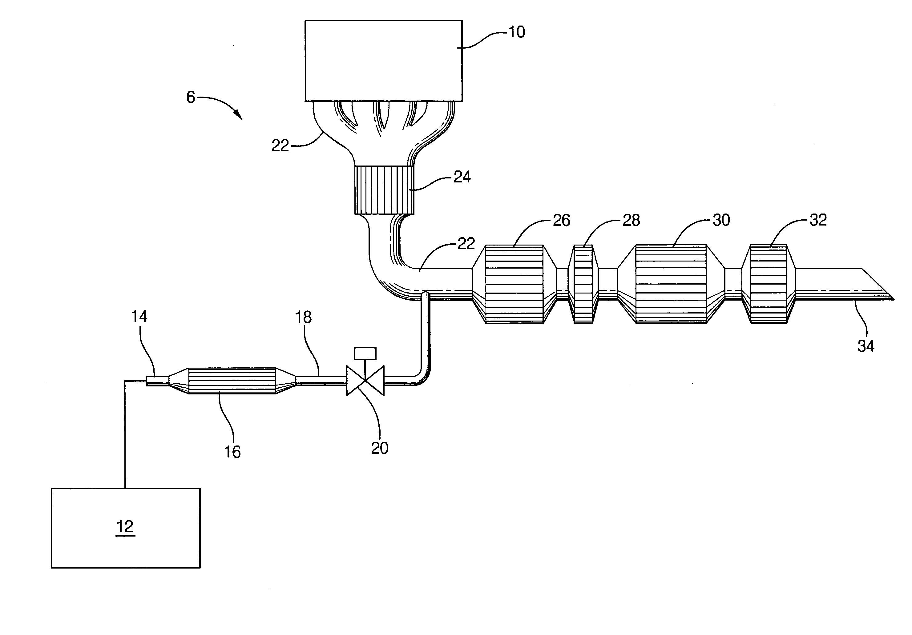
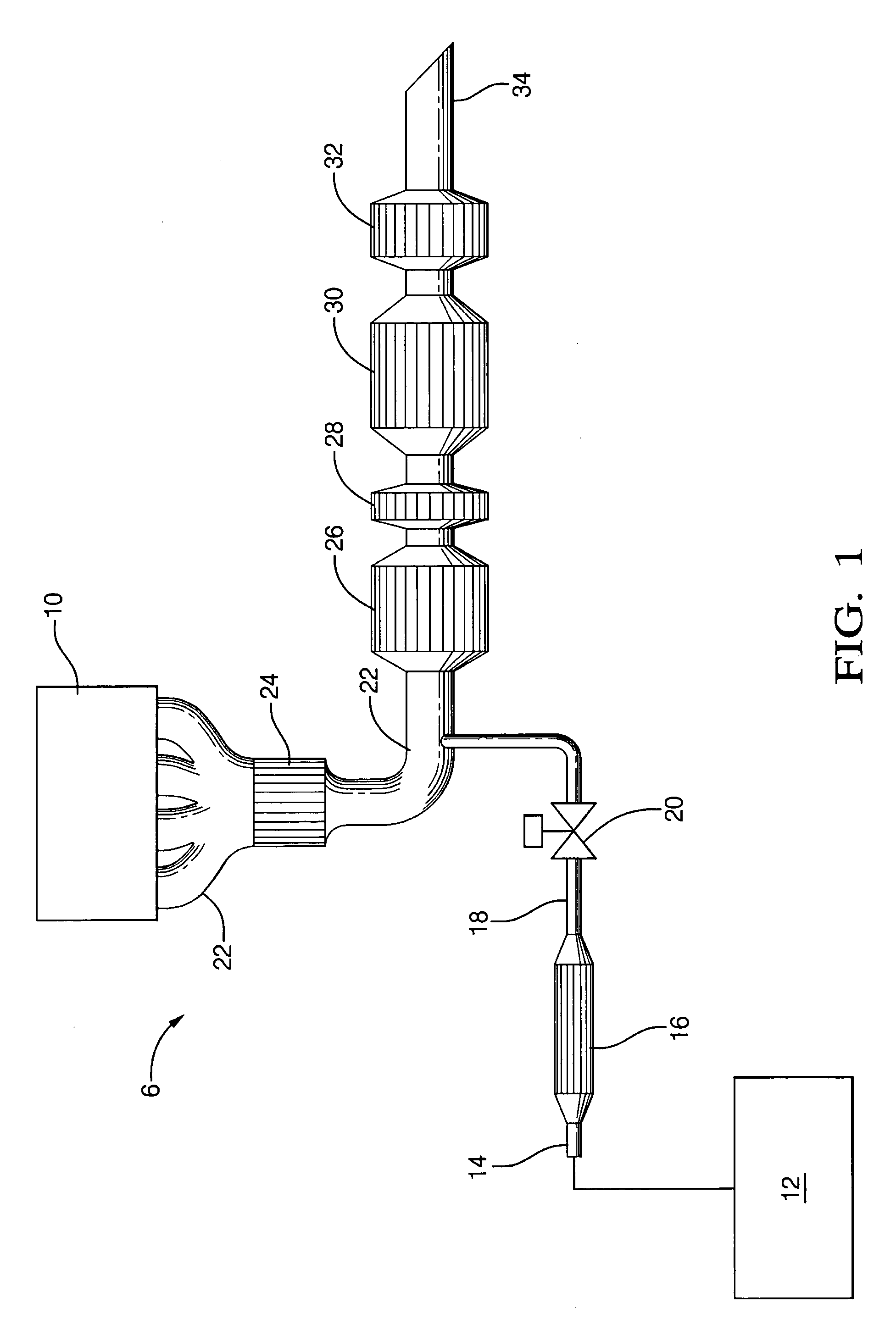
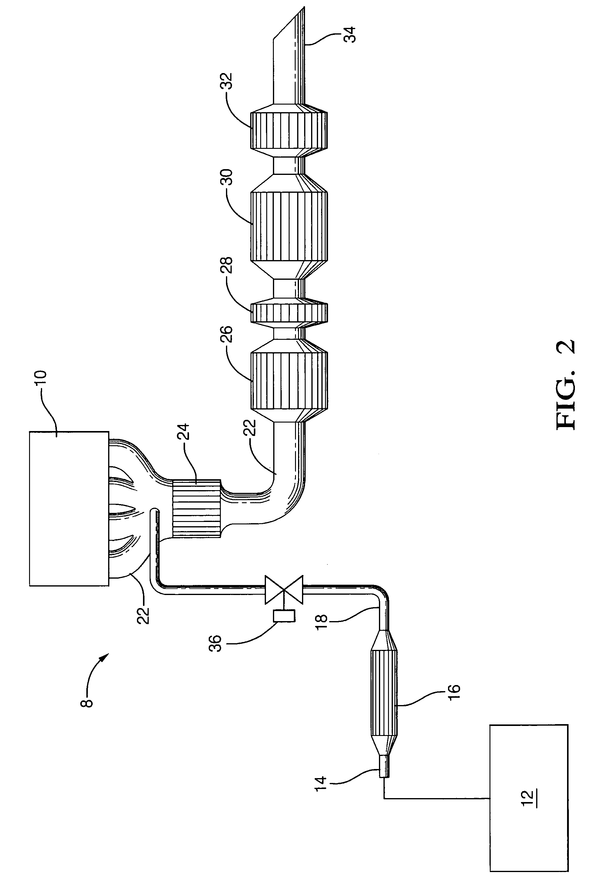
[0018]This disclosure relates generally to a thermal management method and a reducing agent method for efficient reduction of lean exhaust emissions and efficient regeneration of lean exhaust emission components. Relatively cold exhaust temperatures and very little reducing agent characterize engines that produce lean exhaust. By itself, addition of thermal energy to the exhaust stream increa...


PUM

PropertyMeasurementUnit
temperatureaaaaaaaaaa

Abstract

An exhaust system can comprise a NOx adsorber, a reformer disposed upstream of a NOx adsorber and in fluid communication with a fuel source, a first valve for controlling the introduction of the fluid to an exhaust conduit; and a particulate filter disposed upstream and in fluid communication with the NOx adsorber and downstream an in fluid communication with the reformer such that the first valve controls introduction of fluid to the exhaust conduit upstream of the particulate filter. The reformer can be designed to generate a fluid comprising sufficient thermal energy, hydrogen, and carbon monoxide. Optionally, the particulate filter can be designed to be regenerated by the thermal energy and to adsorb a sufficient amount of the thermal energy to reduce the temperature of a gas stream comprising the fluid from a first temperature of about 600° C. to about 1,000° C. to a second temperature of less than or equal to about 500° C.

Description

CROSS REFERENCE TO RELATED APPLICATION[0001]This application is a continuation-in-part of U.S. patent application Ser. No. 10 / 301,455 filed Nov. 21, 2002 now U.S. Pat. No. 6,832,473, which is incorporated herein by reference.BACKGROUND OF THE INVENTION[0002]This disclosure relates to an exhaust system and to thermal energy management and more particularly relates to management of thermal energy flowing into and out of engine exhaust components.[0003]The elimination of hydrocarbons, carbon monoxide, soluble organic fraction, nitric oxide, nitrogen dioxide, nitrous oxide, sulfur oxides, sulfurous oxides, hydrogen sulfide, ammonia and particulates in exhaust gas is a widely addressed problem as a result of environmental concerns and mandated government emissions regulations.[0004]Diesel particulate filters collect particulates from exhaust gas streams. A problem with diesel particulate filters is that they gradually become clogged with particulate matter impeding exhaust flow. The impe...

Claims


Application Information

Patent Timeline
Patent Type & Authority Patents(United States)
IPC IPC(8): F01N3/00B01D53/94C01B3/38F01N3/023F01N3/035F01N3/08F01N3/20F01N13/02
CPCB01D53/9431F01N13/011C01B3/386F01N3/0231F01N3/035F01N3/0885F01N3/103F01N13/02F01N13/0097B01D53/9495B01D2251/202B01D2251/204C01B2203/0261C01B2203/1685F01N2240/30F01N2250/14F01N2610/03F01N2610/04B01D53/9477
Inventor LABARGE, WILLIAM J.KUPE, JOACHIMZIZELMAN, JAMESBOTTI, JEAN J.
Owner DELPHI TECH INC
Learn More