Low cost optical module

Active Publication Date: 2006-08-22
AVAGO TECH INT SALES PTE LTD
View PDF14 Cites 7 Cited by
  • Summary
  • Abstract
  • Description
  • Claims
  • Application Information

AI Technical Summary

Benefits of technology

[0011]Advantageously, the optical module does not require the use of a lens, as the fibre is directly butt coupled to the

Problems solved by technology

An active alignment process in which the fibre is moved into position with respect to the active optical element while the element is powered is both

Method used


Image

  • Low cost optical module
  • Low cost optical module
  • Low cost optical module

Examples


Embodiment Construction

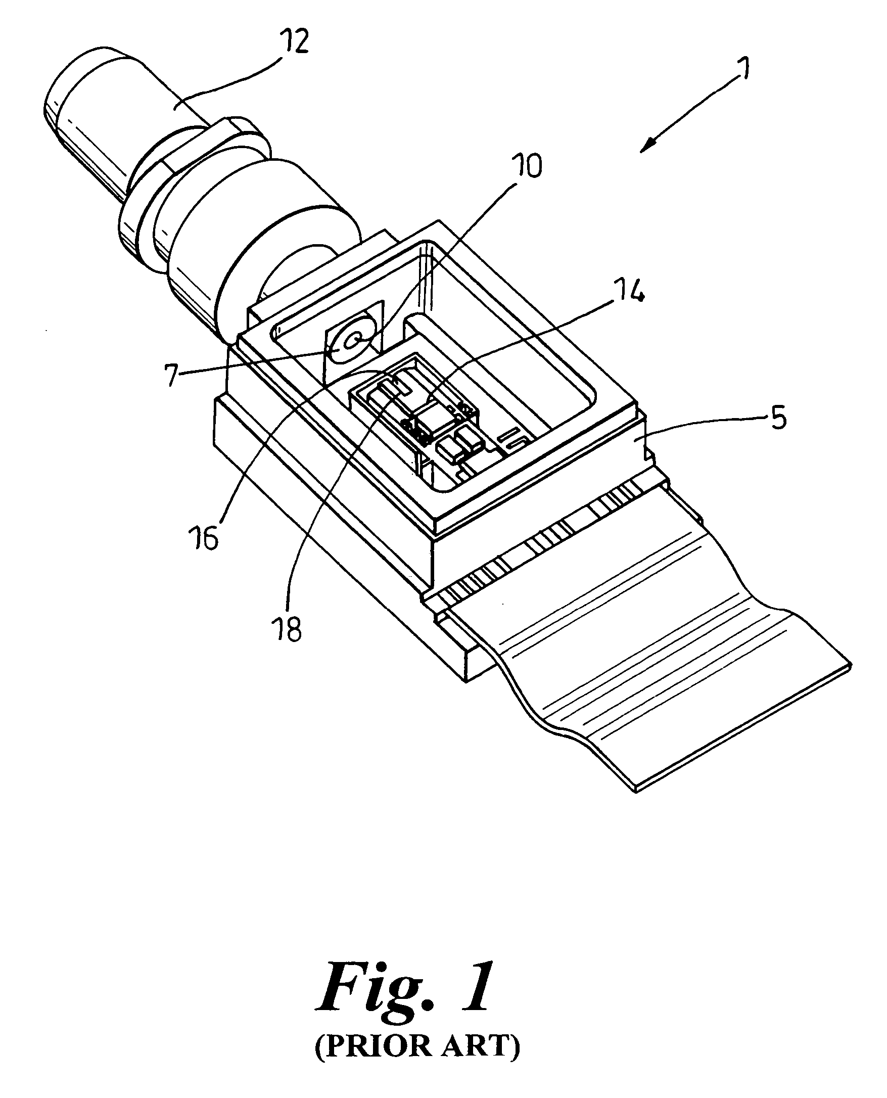
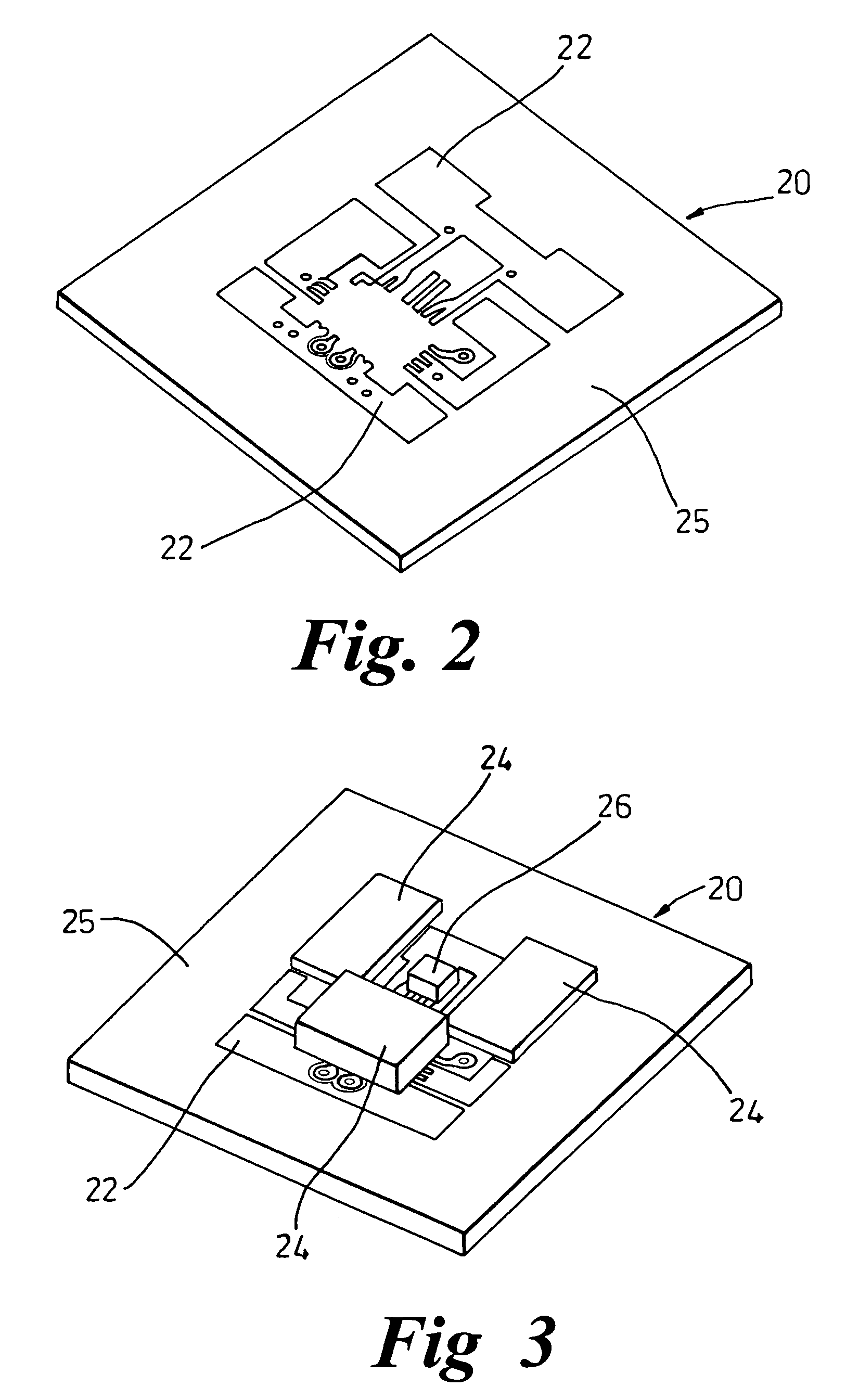
[0022]In FIG. 2 the base plate 20 is a substantially flat tile approximately a few square mm in size and is typically made of a ceramic material with a planarity controlled to within + / −5 um. The use of a ceramic material aids in the distribution of heat generated by any active components placed on the tile. Electrical tracks 22 are disposed on the surface 25 of the tile according to the specific needs of the module. As seen in FIG. 3, various components 24 are attached to the tile at predetermined locations. An active optical component 26 is also disposed on surface 25 of the tile at a predetermined location.

[0023]As will be appreciated, materials other than ceramic can be used, such as plastics or dielectric material, provided sufficient planarity is maintained.

[0024]The components 24 and 26 can be mounted using epoxy or alternatively, ultrasonic bonding. Components 24 and 26 can be than be electrically connected to tracks 22 using wire-bonding methods.

[0025]Alternatively, “flip c...


PUM


Abstract

The present invention comprises an optical module, passively aligned and used in high-speed optical communication systems, having a ferrule disposed in an aperture in an upper plate of the module. The ferrule protrudes a predetermined distance through the aperture in order to guarantee butt coupling of an optical fibre to an active optical component disposed at a predetermined height on a lower plate of the module.

Description

[0001]This application claims benefit of the earlier filed British Application No. GB 0303526.8, Filed Feb. 15, 2003.FIELD OF THE INVENTION[0002]The present invention relates to a low cost package for optical modules. More specifically, the present invention relates to a ceramic passively aligned co-axial package for an optical module used in high-speed optical communication systems.BACKGROUND OF THE INVENTION[0003]As seen in FIG. 1, currently optical modules 1, including transmitters, receivers and transceivers, are packaged in metal or ceramic boxes 5. Alignment between the optical fibre 16 disposed in V groove of a silicon optical bench 18 and an active optical element 14 is achieved using an active optical alignment process implemented during the assembly of the receiver module. The V groove fibre 16 is then coupled to a further fibre 10 located in a ferrule 12 attached to an aperture 7 at one end on the module.[0004]As use of the Internet and optical fibre based communication i...

Claims


Application Information

Patent Timeline
IPC IPC(8): G02B6/42G02B6/38
CPCG02B6/4228G02B6/4202G02B6/3846
Inventor SCOFET, MARCOCONTARDI, CRISTIANASABBATINO, SALVATOREGENISIO, STEFANO
Owner AVAGO TECH INT SALES PTE LTD
Why Eureka
Try Eureka