
Bi-directional optical transceiver module with double caps and method of improving the efficiency and the reliability of same

a transceiver module and bi-directional technology, applied in the direction of optical elements, instruments, semiconductor lasers, etc., can solve the problems of further interference with the electrical signal created in the photodiode, and the time required in assembling the wavelength division multiplexing filter, so as to improve efficiency and reliability.

Inactive Publication Date: 2006-08-22
SAMSUNG ELECTRONICS CO LTD
View PDF10 Cites 47 Cited by
  • Summary
  • Abstract
  • Description
  • Claims
  • Application Information

AI Technical Summary

Benefits of technology

[0016]Accordingly, there is a need to provide a bi-directional optical transceiver module where optical crosstalk or interference between the input and output optical signals are minimized to provide a bi-directional optical transceiver module with improved efficiency and reliability.
[0017]According to one aspect of the invention, a bi-directional optical transceiver module is provided with a wavelength division multiplexing filter that may be more easily mounted.
[0018]According to another aspect of the invention, further efficiency and reliability may be achieved by providing a bi-directional optical transceiver module where the electromagnetic Waves created by the metal lead wires connected to the semiconductor laser do not interfere with the operation of a photodiode converting an optical signal into an electrical signal.
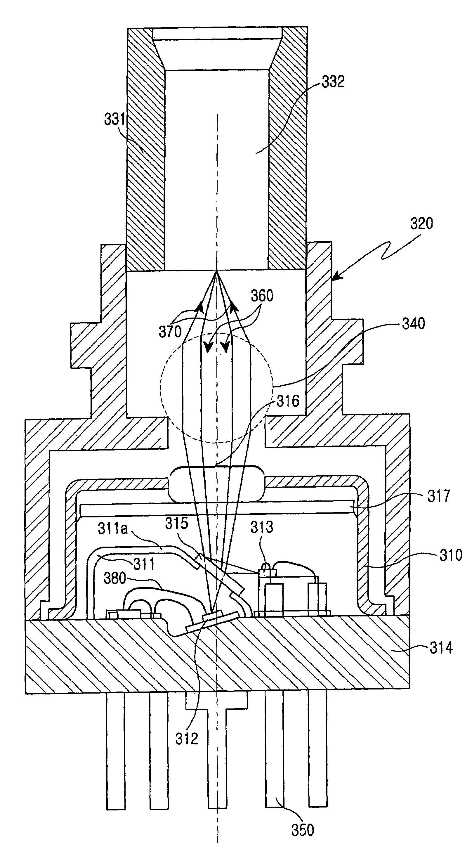
[0019]Accordingly, there is provided a bi-directional optical transceiver module comprising: an optical waveguide element through which input and output optical signals pass; a lens holder in an upper end of which the optical waveguide element is inserted and fixed, the lens holder thereby serving as a body tube; a lens disposed at an upper portion in the lens holder, the lens converging each of the input and output optical signals; a stem supporting a lower end of the lens holder; an outer cap disposed on the stem, the outer cap enclosing a photodiode for receiving an input optical signal and converting it to a corresponding electrical signal; a semiconductor laser for modulating the electrical signal into a corresponding output optical signal; a wavelength division multiplexing filter placed at a location with a predetermined inclination angle where the input and output optical signals intersect one another; and an inner cap mounted within the outer cap isolating the photodiode preventing the electromagnetic waves generated by the metal lead wires of the semiconductor laser from interfering with the operation of the photodiode.

Problems solved by technology

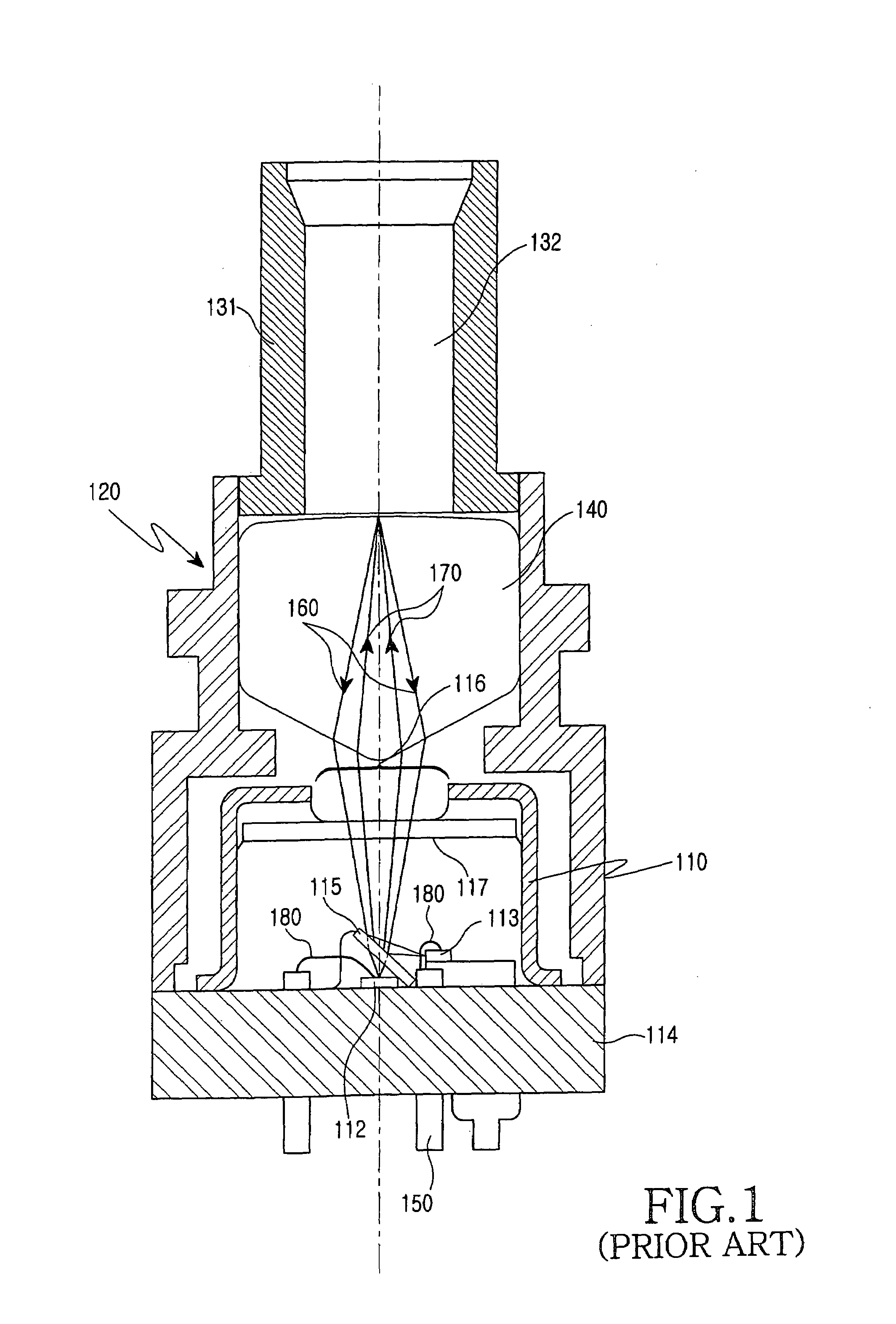
However, in the conventional bi-directional optical transceiver module, much time is required in assembling the wavelength division multiplexing filter, since the wavelength division multiplexing filter must be mounted at a predetermined angle in the optical path of the input and output optical signals.
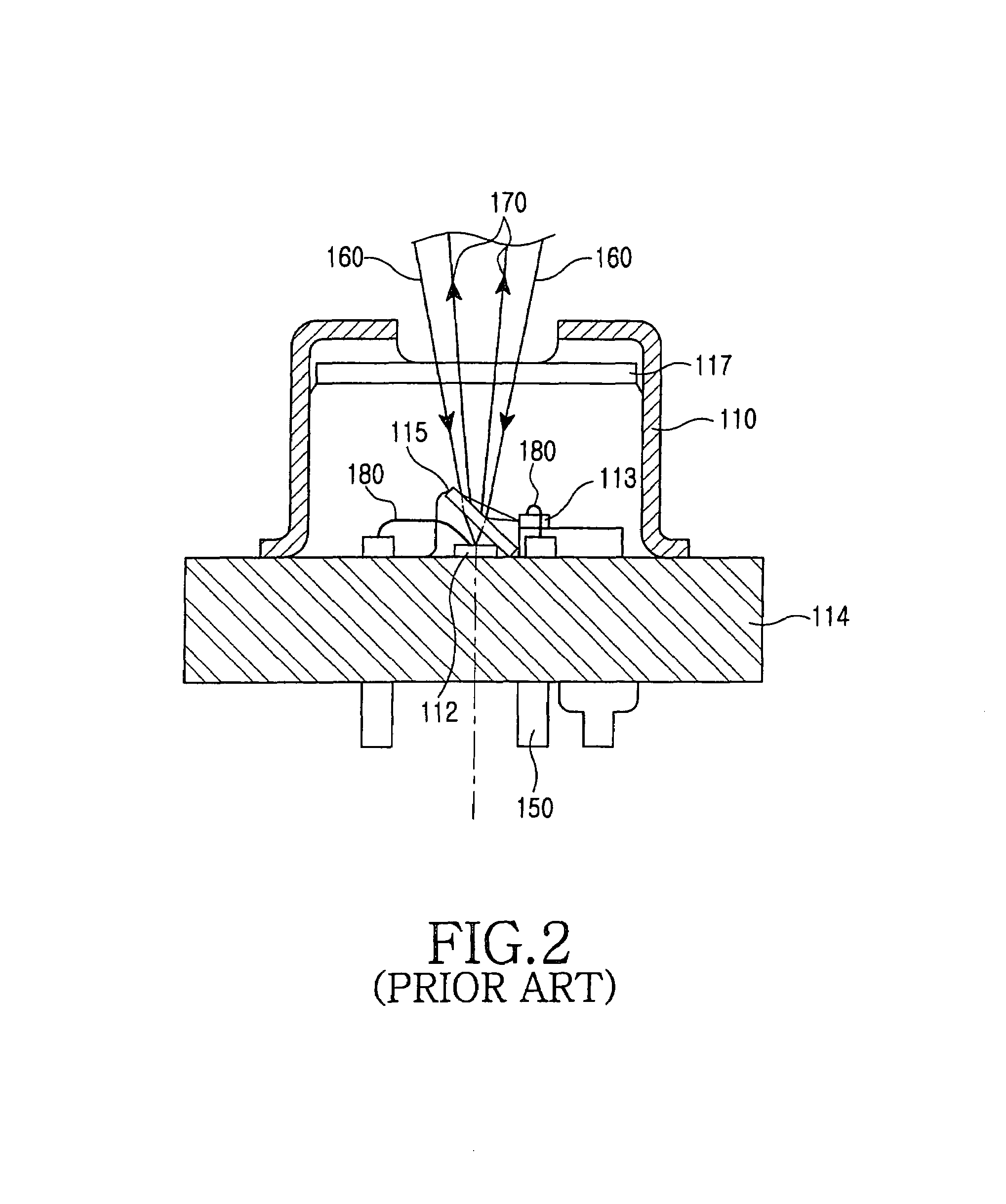
In addition, the electromagnetic waves generated by the lead wires of the semiconductor laser may also be introduced into the photodiode causing further interference with the electrical signal created in the photodiode.

Method used


Image

  • Bi-directional optical transceiver module with double caps and method of improving the efficiency and the reliability of same
  • Bi-directional optical transceiver module with double caps and method of improving the efficiency and the reliability of same
  • Bi-directional optical transceiver module with double caps and method of improving the efficiency and the reliability of same

Examples


Embodiment Construction

[0027]In accordance with the present invention, a preferred embodiment of the present invention will be described with reference to the accompanying drawings. For the purposes of clarity and simplicity, a detailed description of known functions and configurations incorporated herein will be omitted as it may make the subject matter of the present invention unclear.

[0028]Referring to FIG. 3 showing a construction of a bi-directional optical transceiver module having double caps according to a preferred embodiment of the present invention, the bi-directional optical transceiver module includes an optical waveguide element 332, a sleeve 331, a lens holder 320 having a cylindrical construction and serving as a body tube, a lens 340 disposed at an upper portion in the lens holder 320, a stem 314 supporting a lower end of the lens holder 320, an outer cap 310 disposed on the stem 314, and an inner cap 311 mounted in the outer cap 310.

[0029]The optical waveguide element 332 is packaged in ...


PUM


Abstract

The disclosed invention relates to a bi-directional optical transceiver module and method of improving the efficiency and reliability of the same, where interference from optical crosstalk and electromagnetic waves are minimized and a wavelength division multiplexing filter can be easily mounted at a predetermined inclination angle, thereby improving the efficiency and reliability of the bi-directional optical transceiver module.

Description

CLAIM OF PRIORITY[0001]This application claims priority to an application entitled “BI-DIRECTIONAL OPTICAL TRANSCEIVER MODULE WITH DOUBLE CAPS,” filed in the Korean Intellectual Property Office on Oct. 10, 2002 and assigned Serial No. 02-61800, the contents of which are hereby incorporated by reference.BACKGROUND OF THE INVENTION[0002]1. Field of the Invention[0003]The present invention relates to a bi-directional optical transceiver module with double caps. More particularly, the present invention relates to a bi-directional optical transceiver module having double caps in which elements, such as a semiconductor laser and a photodiode, are integrated.[0004]2. Description of the Related Art[0005]Referring to FIG. 1 showing the construction of a conventional bi-directional optical transceiver module, the conventional bi-directional optical transceiver module includes an optical waveguide element 132, a sleeve 131, a lens holder 120 serving as a body tube and having a cylindrical cons...

Claims


Application Information

Patent Timeline
IPC IPC(8): G02B6/42H01L31/02H01S5/022
CPCG02B6/4201G02B6/4204G02B6/4246H01L2224/48137G02B6/4214G02B6/42
Inventor TSUMORI, MASAHIKO
Owner SAMSUNG ELECTRONICS CO LTD
Learn More