

Grinding tool for edge circular processing
a circular processing and grinding tool technology, applied in the direction of manufacturing tools, gear teeth, manufacturing apparatus, etc., can solve the problems of large burden, large burden, and inability to purchase the slab plate whose edges are processed to a predetermined curvature without excess or shortage, etc., to achieve accurate construction by adjustment on site, increase the effect of cost and high precision
- Summary
- Abstract
- Description
- Claims
- Application Information
AI Technical Summary
Benefits of technology
Problems solved by technology
Method used
Image

Examples
first embodiment
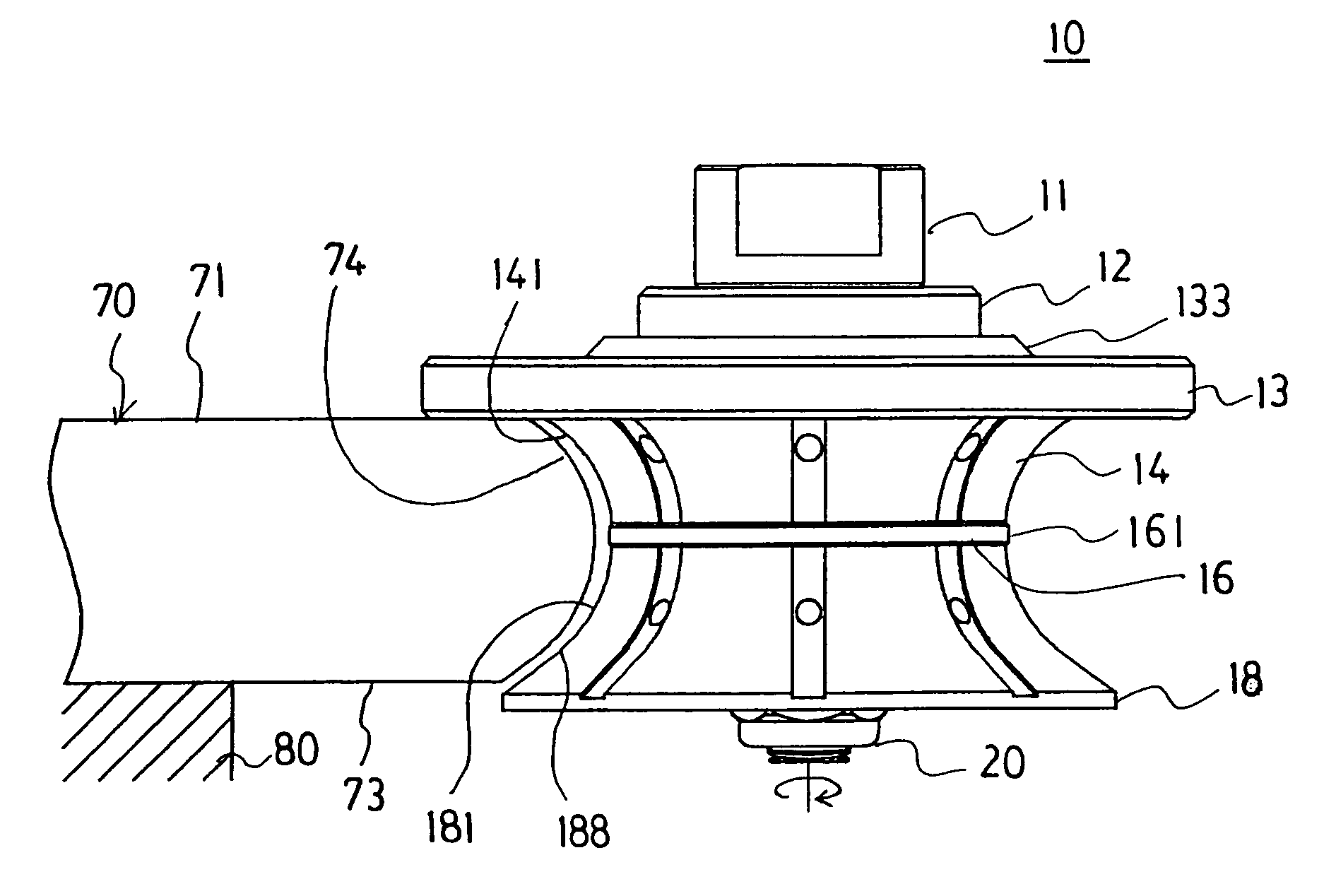
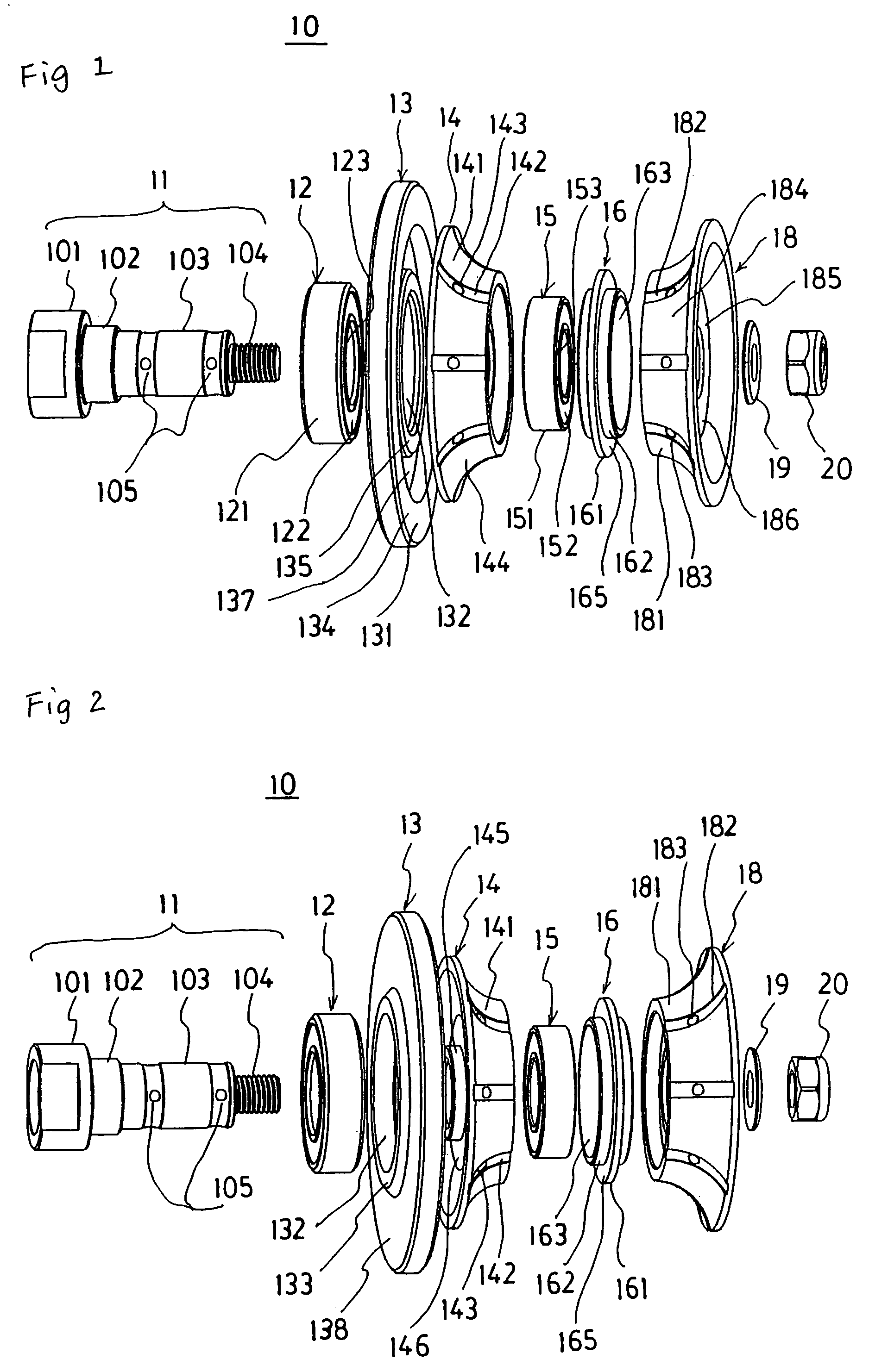
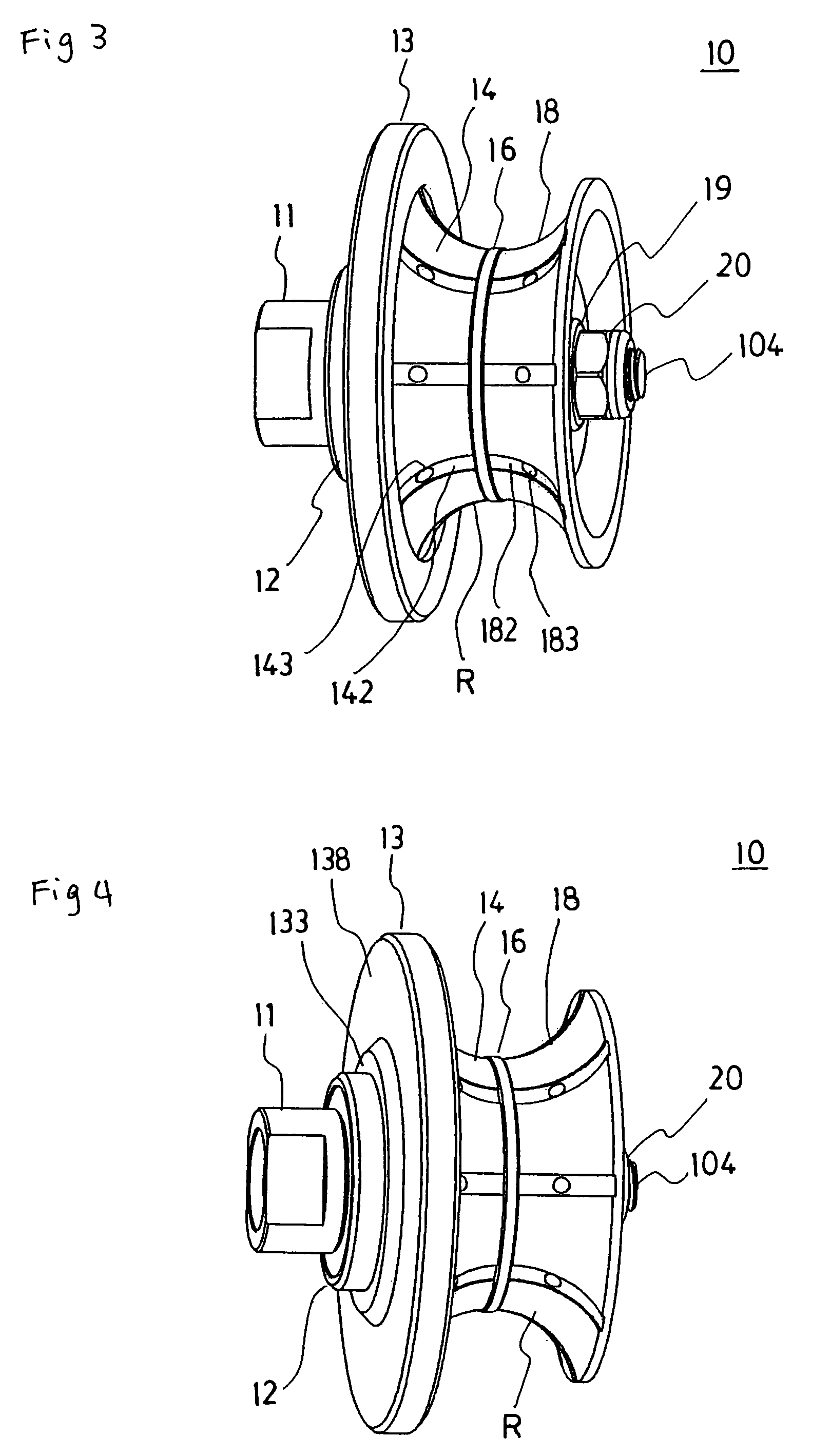
[0046]A marketed hand-held polisher was prepared and respective components formed as shown in FIGS. 1–5 were fitted in and fixed on multiple-stage spindle 11 of the polisher so as to constitute an edge constant angle grinding tool 10. More specifically, to the first spindle main body 102 having an outside diameter of 20.0 mm were fitted the guide plate 13 made of resin having an outside diameter of 96.2 mm and thickness of 7.5 mm in which the first bearing 12 was fitted to the bearing fitting hole 132 and to the spindle main body 103 was fitted the first profile wheel 14 based on the specification described later such that its grinding face 141 was directed forward. Next, the stopper ring 16 was fitted through the second bearing 15 and further the second profile wheel 18 based on the specification described later was fitted to the spindle main body 103 located outside beyond the stopper ring 16 such that its grinding face 181 was directed to the first profile wheel 14. By tightening...
second embodiment
[0050]The full bullnose processing was carried out to three pieces of grinding object materials in the same way as the first embodiment except that the thickness of the grinding object material was set to 32.5 mm instead of 30.8 mm. As shown in photography of FIG. 11, a uniform finish surface approximate to semi-circle was formed in any grinding object material and if the finish surface was observed from obliquely upward, the upper half portion of the semi-circular section, that is, upper ¼ circular section shape was ground into the same shape and it was confirmed that the grinding distance Y as well as the predetermined curvature were controlled precisely.
third embodiment
[0051]The full bullnose processing was carried out on three pieces of grinding object materials in the same way as the first embodiment, except that the thickness of the grinding object material was set to 28.2 mm instead of 30.8 mm. As shown in photography of FIG. 12, a uniform finish surface approximate to semi-circular section shape was formed in any grinding object material and if the finish surface was observed from obliquely upward, the upper half portion of the semi-circular section, that is, upper ¼ circular section shape was ground into the same shape and it was confirmed that the grinding distance Y as well as the predetermined curvature were controlled precisely.
[0052]As a result of arranging grinding object materials which underwent the edge circular processing according to the first-third embodiments in line and observing their end faces from obliquely upward, it was confirmed that the semi-circular upper half portion of the processed edge, that is, the upper ¼ portion ...
PUM
 Abstract
Description
Claims
Application Information