System and method for spacecraft attitude control

Inactive Publication Date: 2006-08-29
BRISTOL AEROSPACE
View PDF12 Cites 20 Cited by
  • Summary
  • Abstract
  • Description
  • Claims
  • Application Information

AI Technical Summary

Benefits of technology

[0069]drive control means responsive to the sensor output for varying the drive output speed so as to maintain the speed of the rotor rotation substantially constant.
[0070]The kinematics of the gimbal assembly cause the rotor angular velocity to oscillate slightly at a frequency of twice the spin rate when the drive is driven at a constant angular velocity. This oscillation produces large loads on the gimbal flexures and also reduces th

Problems solved by technology

To provide redundancy, an additional wheel must be supplied for each axis, a costly and heavy approach.
A major drawback of the multi-wheel configurations is the number of wheels, with attendant redundancy, and the associated duplicated electronic boxes which are needed.
The three actuators are needed to provide some redundancy in each wheel since jack screws can wear and eventually fail.
This limits the pointing acc

Method used


Image

  • System and method for spacecraft attitude control
  • System and method for spacecraft attitude control
  • System and method for spacecraft attitude control

Examples


Embodiment Construction

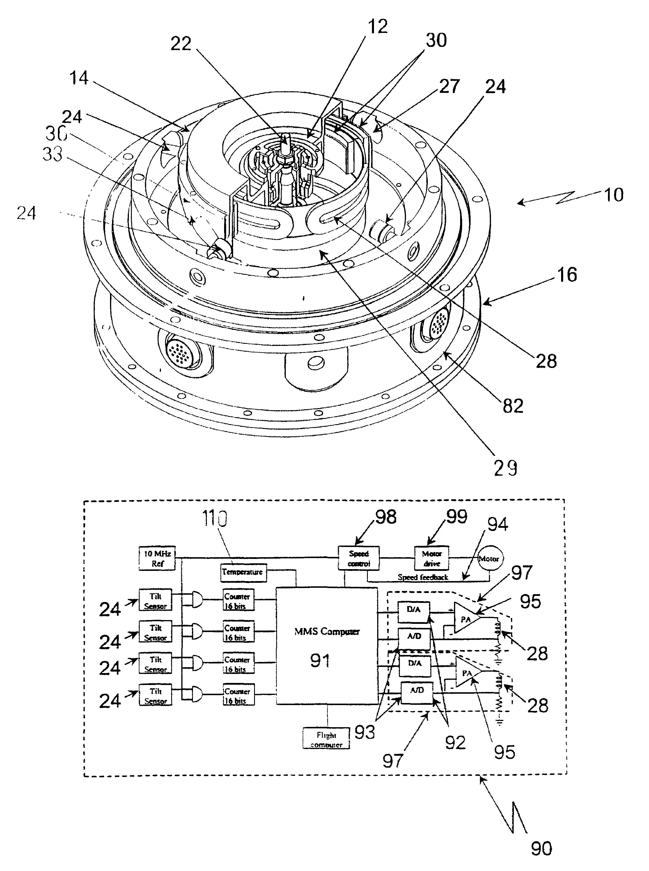
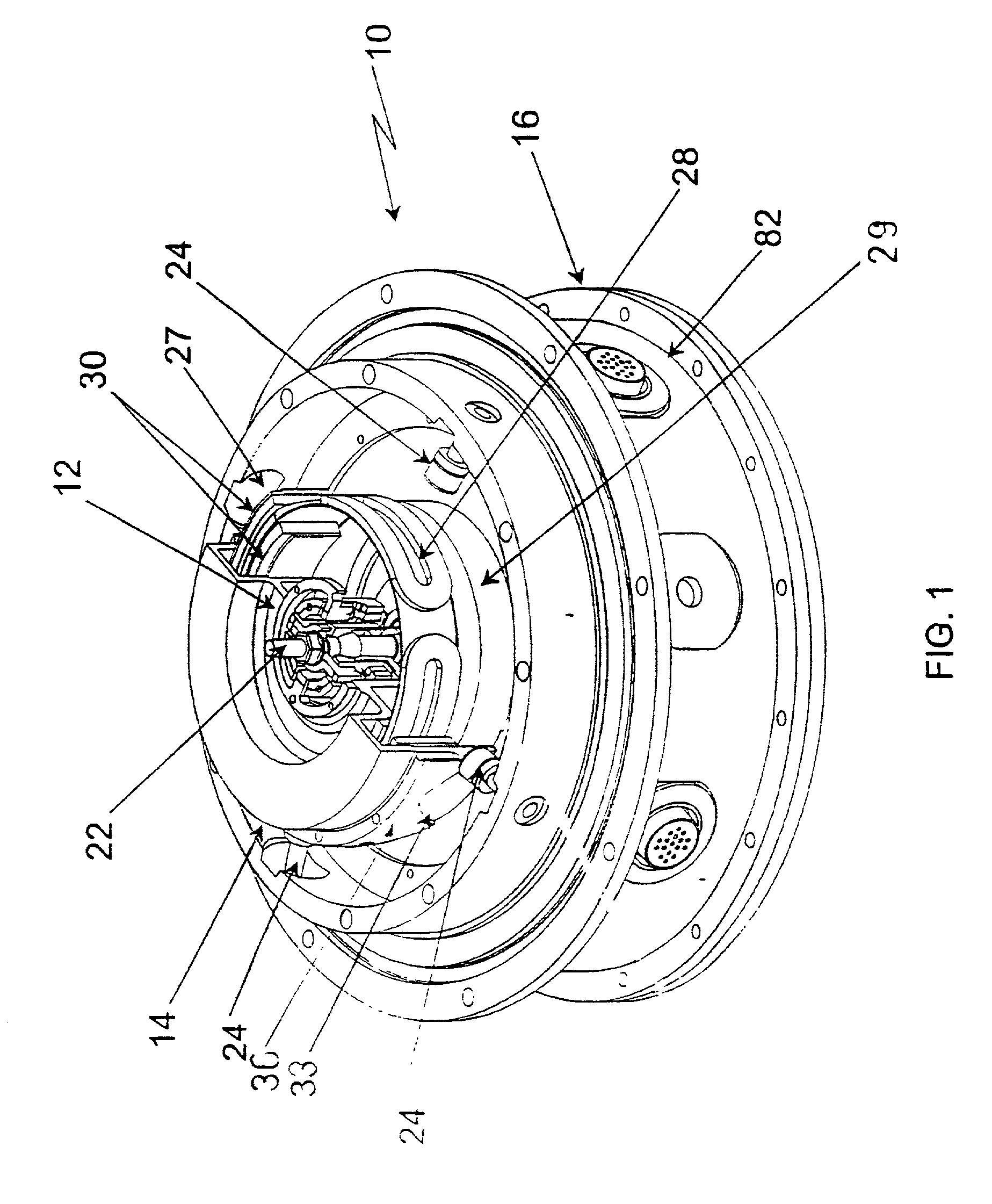
[0095]Embodiments of a momentum management system 10 according to the present invention will now be described with reference to the accompanying drawings. Momentum management system 10 is a form of double gimballed momentum wheel based on a spinning gimbal assembly 12, as opposed to the conventional non-spinning gimbal. A spinning gimbal provides the capability to control the angular momentum about three axes, and to provide two axes of angular velocity measurement at the same time.

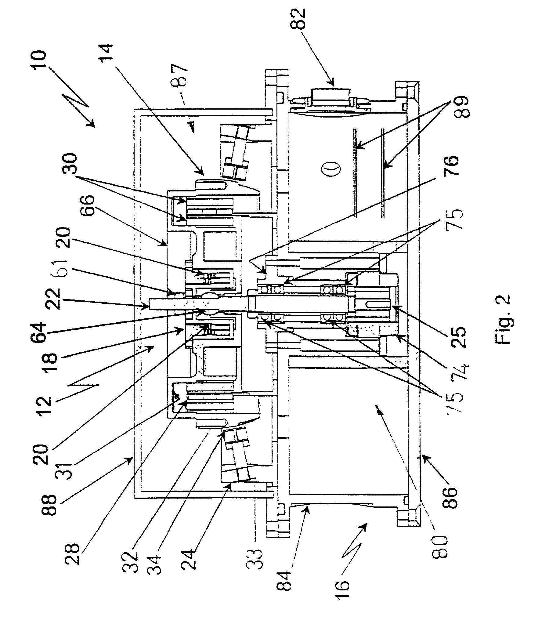
[0096]Referring particularly to FIGS. 1 and 2, system 10 includes a rotor 14 mounted in a housing 16 of non-ferromagnetic material and suspended by a gimbal assembly 12. Gimbal assembly 12 includes a cylindrical gimbal ring 18. Four flexure joints 20 are arranged orthogonally around the ring. The ring is connected through the flexure joints to the rotor 14 and to a drive shaft 22 which is the drive output of a drive 25 including a motor 74 mounted in the housing. The gimbal assembly 12 behaves somewhat li...


PUM


Abstract

A momentum management system for attitude control of a spacecraft includes a housing to be fixed to the spacecraft and a momentum wheel rotor in the housing for storing angular momentum. A gimbal assembly mounts the rotor in the housing. The rotor is driven by a drive with its output coupled to the rotor. A torque generation imparts torque to the rotor about axes orthogonal to the drive axis. The gimbal assembly includes a gimbal ring coupling the drive output to the rotor. The gimbal ring in turn includes flexure joints connecting the gimbal ring to the drive and the rotor. The flexure joints are configured to permit the rotor to tilt about two flexure axes orthogonal to the drive axis to incline the rotor axis through a range of angles from about 0 degrees to about 7 degrees with respect to the drive axis under the control of said torque generation device. The preferred flexure joint is formed from two resilient, crossing webs. The webs have ring ends connected to the body of the gimbal ring and mounting ends connected to either the drive or the rotor. The system includes a launch restraint system to limit movement of the rotor along the drive axis, including a stop mounted on the drive output and a cage mounted on the rotor, surrounding the stop. Under high acceleration, the cage engages the stop to support the rotor, relieving excess stress on the flexures of the gimbal suspension. The launch restraint system also includes deflection stops adjacent opposite sides of each web of each flexure for limiting deflection of the webs.

Description

CROSS REFERENCE TO RELATED APPLICATION[0001]This application is a continuation-in-part of international application PCT / CA99 / 00678, filed Jul. 23, 1999.FIELD OF THE INVENTION[0002]The present invention relates to spacecraft attitude control systems and methods. In particular, the present invention relates to a system and method for momentum management in spacecraft attitude control.BACKGROUND OF THE INVENTION[0003]Spacecraft attitude control systems, such as those used to control the attitudes of satellites, are based on the direct control of angular momentum. The goal of such systems is to point a satellite, or portions of a satellite, at the earth, other celestial bodies, or another spacecraft. Attitude control may be achieved by maintaining a non-zero angular momentum state by including spinning bodies within the spacecraft. Such spacecraft are generally called body stabilized or three axis spacecraft. The present invention is intended for such three axis spacecraft, whether in g...

Claims


Application Information

Patent Timeline
IPC IPC(8): B64G1/28B64G1/32B64G1/36F16D3/56F16D3/72
CPCB64G1/28B64G1/285F16D3/72B64G1/32B64G1/36F16D3/56B64G1/283B64G1/286
Inventor STALEY, DOUGLAS A.TYC, GEORGEFRISE, PETER R.
Owner BRISTOL AEROSPACE
Why Eureka
Try Eureka