Method and means for processing oil sands while excavating

a technology of oil sands and extraction methods, applied in the direction of mining structures, drilling machines and methods, surface mining, etc., can solve the problems of substantial disturbance of the surface, inability to economically exploit traditional oil well technology, and significant increase in the overall cost of bitumen recovery, so as to achieve more efficient removal, reduce greenhouse gas emissions, and enhance the effect of some aspects of the extraction process

Inactive Publication Date: 2006-08-29
OSUM OIL SANDS CORP
View PDF66 Cites 29 Cited by
  • Summary
  • Abstract
  • Description
  • Claims
  • Application Information

AI Technical Summary

Benefits of technology

[0117]As noted previously, substantial methane and carbon dioxide are dissolved in in-situ bitumen at formation conditions. This dissolved gas is a significant greenhouse gas source if liberated into the atmosphere. This gas can, however, assist the extraction of bitumen from the oil sands if it remains dissolved and attached to the bitumen particles. By operating a bitmin drum at formation pressure, the gases contained in the oil sands can be used to promote separation of the water and bitumen. This is because water and bitumen have densities that are very similar (both about 1,000 kg / m3) and the gases dissolved and attached to the bitumen particles lower its density and allow it to float to the surface as, for example, required by most of the separation processes practiced in the Athabasca oil sands industries. Further the gases can be captured during the separation process so that they can be prevented from escaping to the atmosphere and contributing to other emitted greenhouse gases. The ability to operate the bitmin drum in a closed and pressurized mode another advantage of the present invention.
[0118]FIGS. 8a and b show a bitmin drum such as described in Canadian Patent 2,124,199. This is an example of a counterflow de sander apparatus 10. In FIG. 8a, oil sands ore is fed in via the conduit 46 at the front end while heated water is injected in via conduit 50 at the back end. Solids discharge (tailings) are discharged from the back end via conduit 44 while a lean bitumen froth (the valuable product) is collected at the front end via conduit 52. FIG. 8b shows the internal spiral paddle 14 and other devices which set up the flow required to preferentially separate the bitumen from the oil sands by ablation while passing the lumps of clay with little ablation as described, for example, in Canadian Patent 2,124,199. FIGS. 9a and b show end views of the bitmin drum. FIG. 9a shows the front end where the ore is fed in while FIG. 9b shows the rear end where heated water is injected.
[0119]FIG. 10, which is prior art, shows a schematic of a typical slurry TBM cutter head drive system and muck conveyor apparatus as described in “Mitsubishi Shield Machine”, sales brochure, Mitsubishi Heavy Industries, Ltd, Construction Machinery Division, No. 84-11, 1984. The cutter head is rotated by a large ring mounted in the bulkhead. The ring is driven by a series of hydraulic motors mounted around the bulkhead. For example, a TBM with a 7-meter diameter cutter head may have somewhere between 10 and 18 such hydraulic motors. The alignment of the cutter head is maintained by a central shaft which is mounted at the center of the cutter head and passes through a pressure bulkhead utilizing a rotary joint. The rotary joint is used, for example, to pass slurry additives, water and hydraulic fluids to the cutter head. The muck or excavated material is collected near the bottom of the cutter head and conveyed through the pressure bulkhead, for example, by a screw auger. In this schematic, the screw auger maintains a pressure differential across its length. This is typical of slurry and Earth Pressure Balance (“EPB”) TBMs used for civil construction projects.
[0120]FIG. 11 shows a schematic flow diagram for a combined TBM and bitmin drum apparatus. The principal elements of the system are the TBM cutter head 1301, the bitmin drum 1302, a backfill apparatus 1305 and a heat exchanger apparatus 1306. Appropriately clean water is fed into the system along path 1311 and is heated as it passes through the heat exchanger 1306. The clean water is conveyed into the machine from the surface through an access tunnel (not shown, but formed behind the advancing TBM as described in U.S. patent application Ser. No. 09 / 797,886). The heat required for the heat exchanger 1306 can come from any heat source such as, for example, from the waste heat from the TBM motors and hydraulics. A fraction of the heated water is injected into the bitmin drum 1302 along path 1312. The remainder of the heated water is supplied to the TBM cutter head 1301 along path 1313. The water supplied to the TBM cutter head 1301 may be used for water jets to aid the cutting action or to form a cutting slurry ahead of the cutter head or both. Oil sands ore is produced at the cutter head 1301 either as a dry ore or as a damp or wet slurry and enters the cutter head 1301 along path 1314. The oil sands ore is fed into the bitmin drum 1302 along path 1315. Inside the bitmin drum 1302, the ore is processed to produce, in part, a solids discharge which is removed via path 1316. Most of the solids discharge is routed to the backfill apparatus along path 1318 where it is injected as backfill behind the TBM via path 1319. A small portion of the solids discharge may be excess and is removed through the trailing access tunnel (not shown, but formed behind the advancing TBM as described in U.S. patent application Ser. No. 09 / 797,886) via path 1317. The ore in the bitmin drum 1302 is also processed, in part, to produce a bitumen froth (mixture of water and bitumen) which is collected and removed through the trailing access tunnel via path 1329 to a separation cell (not shown) located typically on the surface. The separation cell, of which several types exist, separates most of the water from the bitumen. Some water is recovered from the cutting slurry inside the cutting head 1301 and is removed through the trailing access tunnel via path 1322 to a water conditioning unit (not shown) located typically on the surface. The water removed from the cutter head to the surface via path 1322 and the water recovered from the separation cell is available for reuse after being properly conditioned and can be added to the water being supplied along path 1311.
[0121]FIG. 12 shows a schematic side view of a preferred embodiment of the present invention focusing on the main elements of the invention and the location of the principal material inputs and outputs. The major components of the system are the TBM cutter head 1400, the TBM shield 1401 and the bitmin drum 1402. Oil sands ore is formed in front of the cutter head 1400, passed through the cutter head 1400 into the TBM slurry chamber 1403 and fed into the bitmin drum 1402 through, for example, a screw auger system 1404. Water is fed into the bitmin drum 1402 through a conduit 1405 in the opposite direction to the ore feed in order to develop the counterflow desanding action. Solids are separated from the ore feed inside the bitmin drum 1402 and are collected and discharged through conduit 1406. Liquids, called a bitumen froth and consisting primarily of bitumen and water, are also separated from the ore feed inside the bitmin drum 1402 and are collected and discharged through conduit 1407. The components described above all containing on a pressurized side 1408 separated from the non-pressurized side 1411 by a bulkhead 1409. The water feed 1405, the soil discharge feed 1406 and the bitumen froth feed 1407 all pass through the bulkhead 1409 via sealed connections. The pressure on the pressurized side 1408 of the bulkhead 1409 is typically maintained at or sightly above formation pressure so that the methane and other gases dissolved in the oil sands ore is prevented from exsolving into the pressurized chamber.
[0122]The bulkhead 1412 between the slurry chamber 1403 and the bitmin drum 1402 may also be a pressure bulkhead as is typically the case, for example, in a slurry TBM used in civil tunneling projects. This would allow the side 1408 to be de-pressurized, for example to perform maintenance on the bitmin drum.

Problems solved by technology

Oil Sands deposits cannot be economically exploited by traditional oil well technology because the bitumen or heavy oil is too viscous to flow at natural reservoir temperatures.
In the large surface mining process described above, there is substantial disturbance of the surface.
This requirement adds significantly to overall bitumen recovery costs.
Thus the economics of these processes are sensitive to the complex and variable natures of the reservoir geologies that are found.
The production of energy to produce steam also contributes significantly to greenhouse gas emissions.
There is currently no viable means to recover the bitumen or heavy oil from these “no man's” land areas.
Earlier methods, such as the Clark process, used temperatures of 85° C. and above together with vigorous mechanical agitation and are highly energy inefficient.
The separation process particularly is quite complex, as will be readily apparent from a study of U.S. Pat. No. 4,946,597, and certain phases have presented particularly intractable problems.
Oil sands typically contain substantial but variable quantities of clay, and the very fine particles constituting this clay are dispersed during the process, limiting the degree to which the water utilized in the process can be recovered by flocculation of the clay particles.
No economical means has been discovered of disposing of the flocculated and thickened clay particles, which form a sludge which must be stored in sludge ponds where it remains in a gel-like state indefinitely.
The Clark process has disadvantages, some of which are discussed in the introductory passage of U.S. Pat. No. 4,946,597 which is incorporated herein by reference, notably a requirement for a large net input of thermal and mechanical energy, complex procedures for separating the released oil, and the generation of large quantities of sludge requiring indefinite storage.
Nevertheless, it continues to regard external mechanical action as playing an essential role in the disintegration of the oil and granules, which will inevitably result in partial dispersion of the clay.
The cyclo-separator has a number of major disadvantages including but not limited to (i) the need to commute large rocks and remove contaminants, such as wood and tramp metal, from input streams to avoid damaging the cyclo-separator; (ii) high rates of equipment wear and the concomittant need to use expensive abrasion resistant materials; (iii) de-aeration of the recovered bitumen which causes problems for downstream stages of separation; and (iv) cyclone failure or viscous plugging due to a black froth condition for high bitumen content ores.
All studies to-date have led to the abandonment of the hydro-cyclone solution, even in very large fixed separation facilities.
Even with the bitumen removed, the sand grains cannot be reconstituted into their original volume even under tremendous pressure.
Thus, current surface mining methods result in a large and costly tailings disposal problem.
The extraction process for removing the bitumen from the ore requires substantial energy.

Method used


Image

  • Method and means for processing oil sands while excavating
  • Method and means for processing oil sands while excavating
  • Method and means for processing oil sands while excavating

Examples


Embodiment Construction

Bitumen Separation Using Variations of the Clark Process

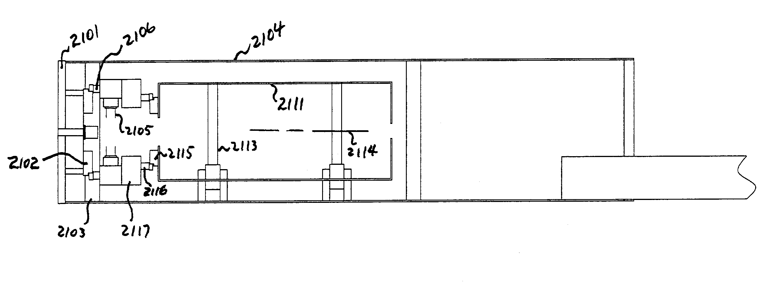
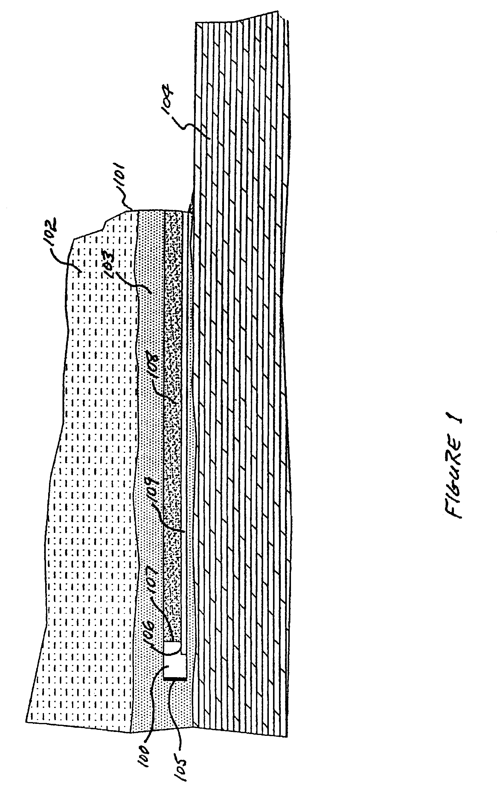
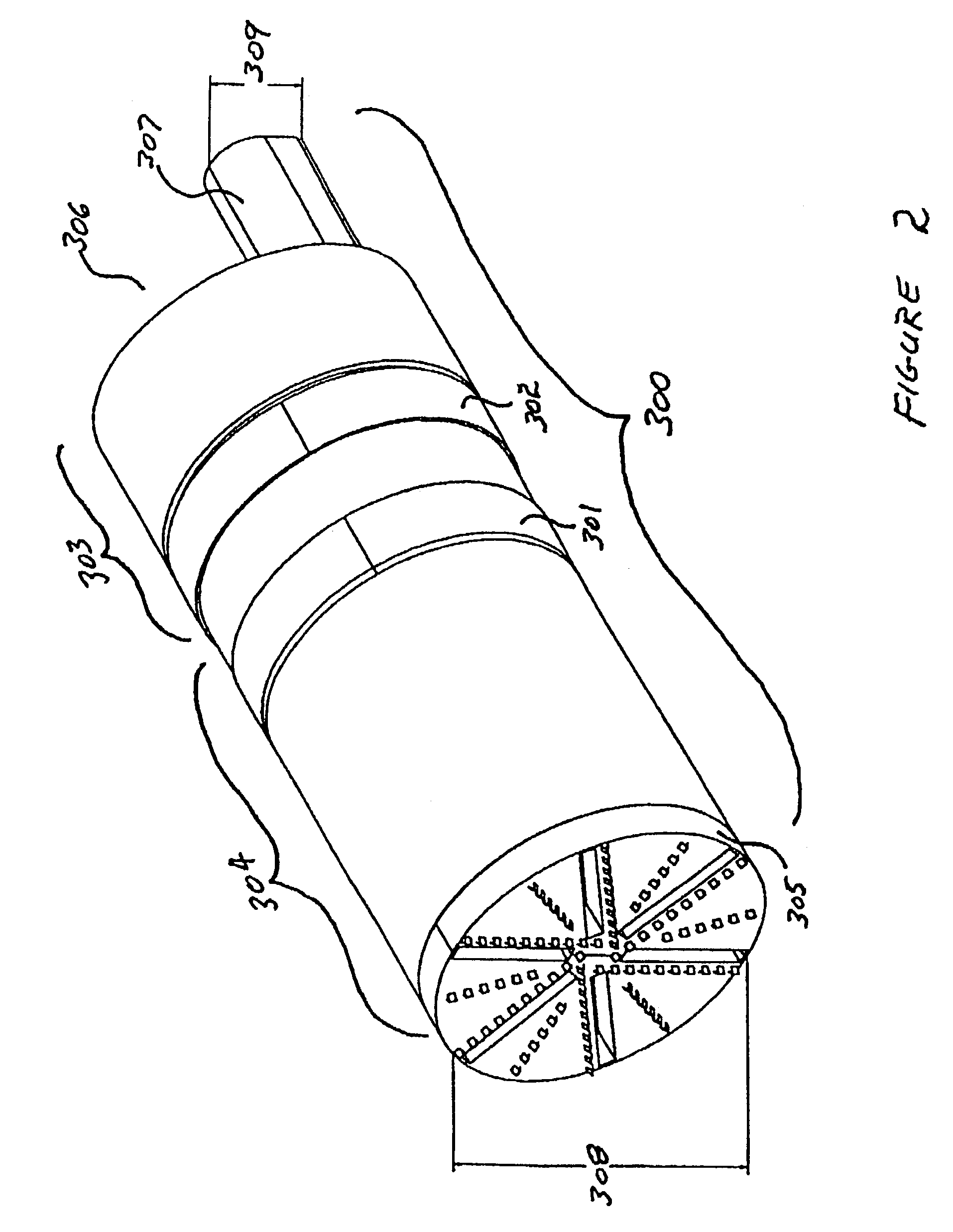
[0070]In one embodiment, the present invention includes a shielded mining machine that excavates oil sand material by using a combination of mechanical cutters, water jets and the action of a hot water slurry and a chamber for performing bitumen separation using a variation of the Clark process. The mechanical agitation of the hot slurry reduces the size of the clumps of oil sand and other material while the combination of mechanical agitation and hot water causes the bitumen to begin separating from the sand grains. When the material reaches a desired size, it is ingested through a rotating cutter head into a pressure chamber. The pressure chamber is formed by the rear of the rotating cutter head, an outer shield and a pressure bulkhead. Additional hot water and air may be added to the slurry in the pressure chamber, The material remains in the pressure chamber where it continues to be agitated by the rotation of the cutter he...


PUM


Abstract

The present invention is directed to the separation of bitumen, such as by the Clark process or by a countercurrent de-sander, in an underground excavation machine, such as a tunnel boring machine.

Description

CROSS REFERENCE TO RELATED APPLICATIONS[0001]The present invention claims the benefits of U.S. Provisional Applications Ser. Nos. 60 / 347,348, filed Jan. 9, 2002, and 60 / 424,540, filed Nov. 6, 2002, each of which is incorporated herein by reference in its entirety.FIELD OF THE INVENTION[0002]The present invention is related generally to extracting bitumen from excavated oil sands and particularly to extracting the bitumen from the excavated oil sands in a shielded underground mining machine.BACKGROUND OF THE INVENTION[0003]There are substantial deposits of oil sands in the world with particularly large deposits in Canada and Venezuela. For example, the Athabasca oil sands region of the Western Canadian Sedimentary Basin contains an estimated 1.3 trillion barrels of potentially recoverable bitumen. There are lesser, but significant deposits, found in the U.S. and other countries. These oil sands contain a petroleum substance called bitumen (similar to an asphalt) or heavy oil (a highl...

Claims


Application Information

Patent Timeline
Patent Type & Authority Patents(United States)
IPC IPC(8): E21C41/24E02F7/00E21B1/00E21D9/08E21D9/12E21D9/13
CPCE21C41/24E21D9/13E21D9/11E21D9/081E21D9/0879
Inventor DRAKE, RONALD D.KOBLER, MICHAEL HELMUTWATSON, JOHN DAVID
Owner OSUM OIL SANDS CORP
Why Eureka
Try Eureka