Bearing support

a technology of bearings and supports, applied in the direction of bearing unit rigid supports, turbine/propulsion lubrication, liquid fuel engine components, etc., can solve the problems of normal and abnormal loading of bearing systems, imbalance of associated rotors, and inability to spool down

Active Publication Date: 2006-08-29
RTX CORP
View PDF8 Cites 64 Cited by
  • Summary
  • Abstract
  • Description
  • Claims
  • Application Information

AI Technical Summary

Problems solved by technology

The bearing systems are subject to normal and abnormal loading.
One particularly severe source of abnormal loading in a turbofan engine is a fan blade-out or blade-off (FBO) event wherein an entire blade or substantial portion of its airfoil is shed, thereby imbalancing the associated rotor.
In typical aircraft applications, such a spooldown is not practical as a stopped engine constitutes and extreme source of aerodynamic drag.
Such drag is particularly significant in twin-engine aircraft wherein the engines are mounted in wing nacelles.
Thus, in such twin-engine aircraft, the combination of drag from the stopped engine and thrust from the remaining engine will produce an excessive yawing moment not easily overcome by the aircraft rudder.
The potentially damaging imbalance forces are transmitted from the windmilling rotor through the bearings to the support frame.
Unfortunately, such strengthening of the bearings and support frame adds undesirable weight and bulk to the engine and aircraft.
However, the imbalance forces at the beginning of spool-down may be excessive given the relatively high initial speed (e.g., a cruise speed of 2000–2500 rpm) since such forces are proportional to the square of the speed.
The engine is still subject to significant radial displacement of the rotor and associated flexing of the shaft.
The imbalance forces and displacements during the various transitions and thereafter may still subject the engine and aircraft to excessive loading and undue sympathetic vibration.

Method used


Image

  • Bearing support
  • Bearing support
  • Bearing support

Examples


Embodiment Construction

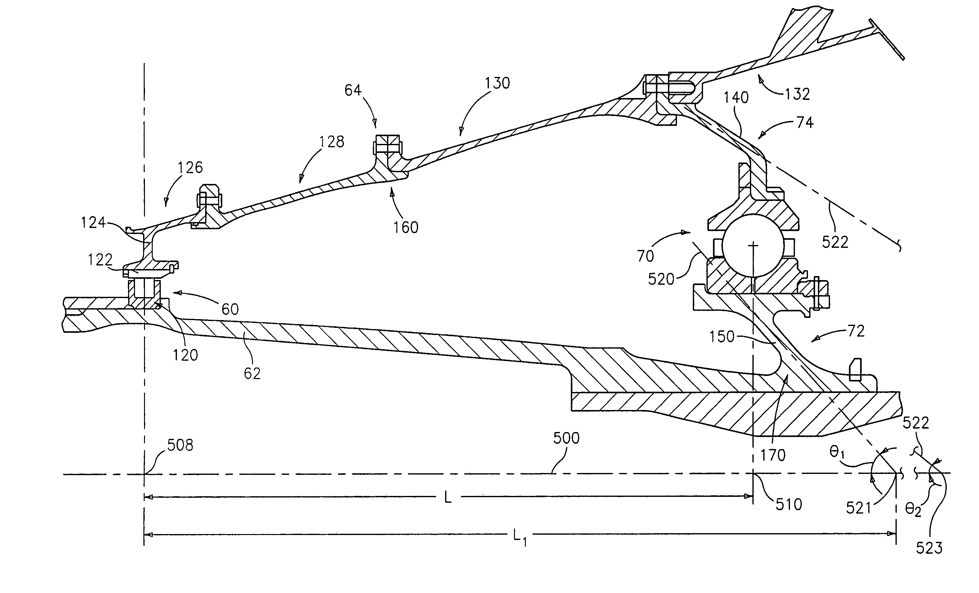
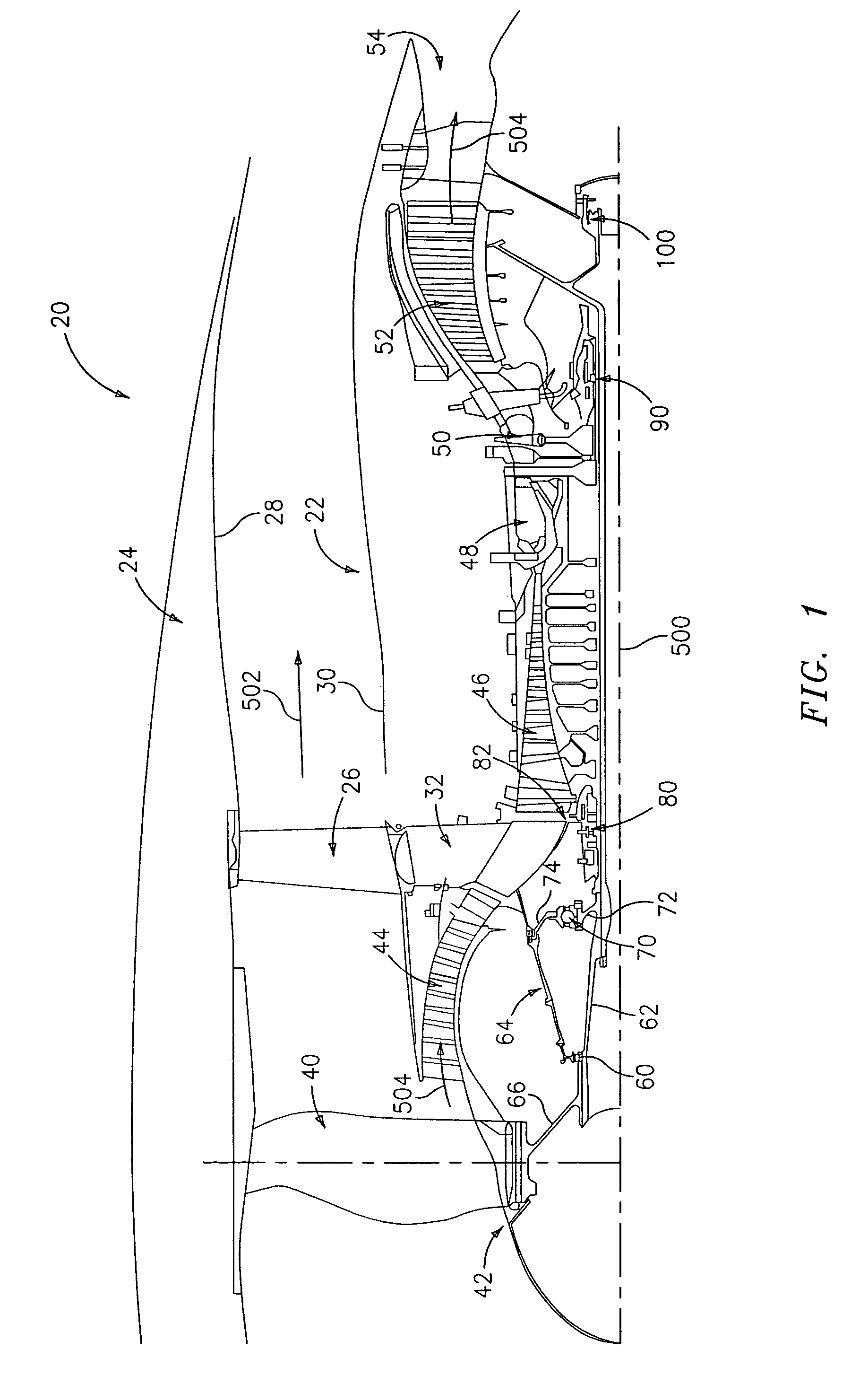
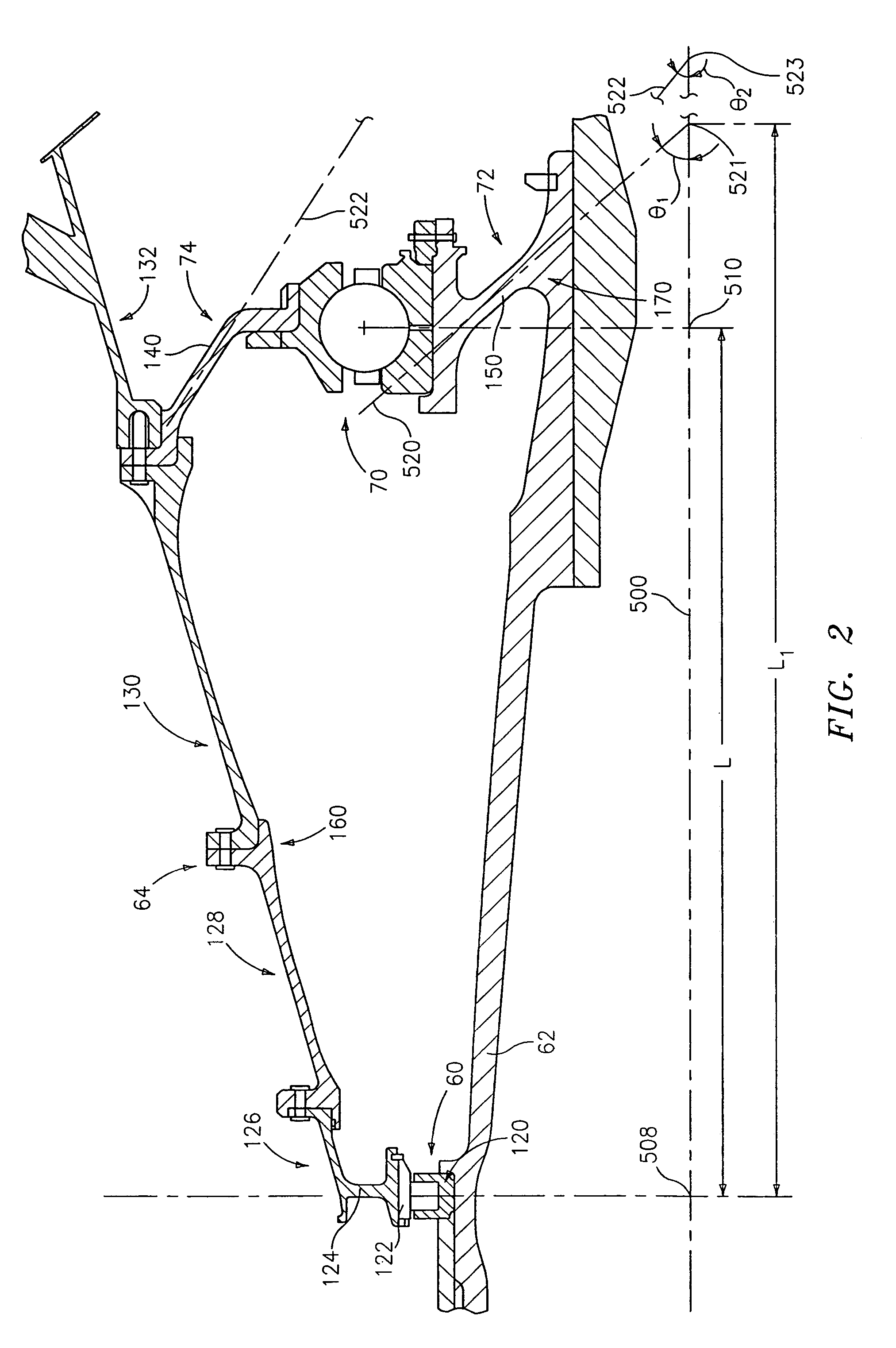
[0021]FIG. 1 shows an exemplary turbofan engine 20 having a central longitudinal axis or engine centerline 500. The engine includes a core 22 mounted within a nacelle 24 with a generally annular bypass flowpath 502 therebetween. The core is supported relative to the nacelle by a circumferential array of struts 26 extending between a nacelle inner surface 28 and a core outer surface 30. The struts 26 are supported on a strut hub 32 of a core non-rotating engine case structure.

[0022]The bypass flowpath 502 extends downstream from a fan having a number of blades 40 on a hub 42. In the exemplary embodiment, the fan is mounted on the low speed spool of a two-spool system. Downstream from the fan along the core flowpath 504 is a low speed / pressure compressor section 44 whose blades are on the low speed spool. Further downstream is a high speed / pressure compressor section 46 whose blades are on the high speed spool. Further downstream is a combustor 48. Further downstream is a high speed / p...


PUM


Abstract

To further isolate imbalances in a rotating structure such as a gas turbine engine, an effective length between two bearings may exceed an actual length. This may be achieved via one or more tapering bearing supports associated with at least one of the bearings.

Description

BACKGROUND OF THE INVENTION[0001](1) Field of the Invention[0002]This invention relates to bearings, and more particularly to bearing supports in turbomachinery.[0003](2) Description of the Related Art[0004]The use of bearings to support relatively rotating turbomachine structures is a well developed art. In common turbomachine applications, a series of coaxial bearing systems support one or more rotating structures (rotors) for normal rotation about the common axis relative to a stationary structure (stator). The bearing systems are subject to normal and abnormal loading. Normal loading may include various static forces and routine dynamic forces including vibration and transient forces associated with changes in operating condition. Abnormal loads may include those associated with damage, including foreign object damage (FOD) to any of the various rotating blades of the fan, compressor section(s), and turbine section(s). One particularly severe source of abnormal loading in a turb...

Claims


Application Information

Patent Timeline
Patent Type & Authority Patents(United States)
IPC IPC(8): F01B25/16F01D21/04F01D25/16F02C7/00F02C7/06F02K3/06F16C27/04F16C35/07
CPCF01D21/08F16C27/04F01D25/16Y02T50/671F16C2360/23Y02T50/60F01D25/00
Inventor VANDUYN, KEVEN G.
Owner RTX CORP
Why Eureka
Try Eureka