Electro-optical device and method for manufacturing the same
- Summary
- Abstract
- Description
- Claims
- Application Information
AI Technical Summary
Benefits of technology
Problems solved by technology
Method used
Image
Examples
example 1
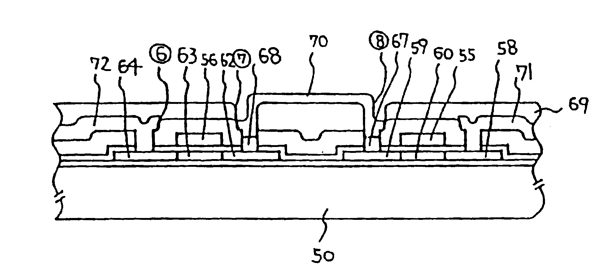
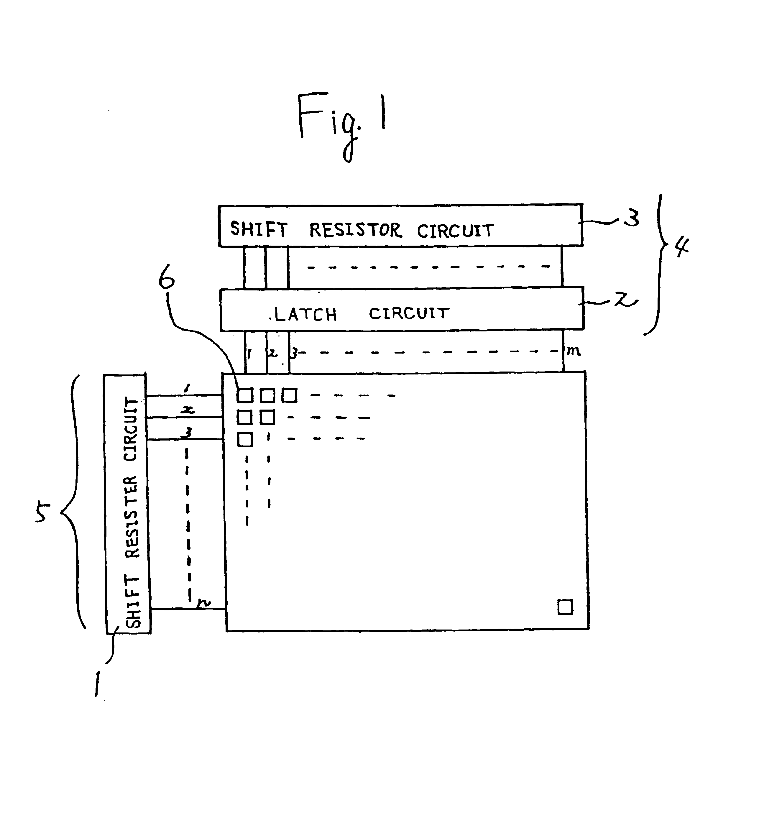
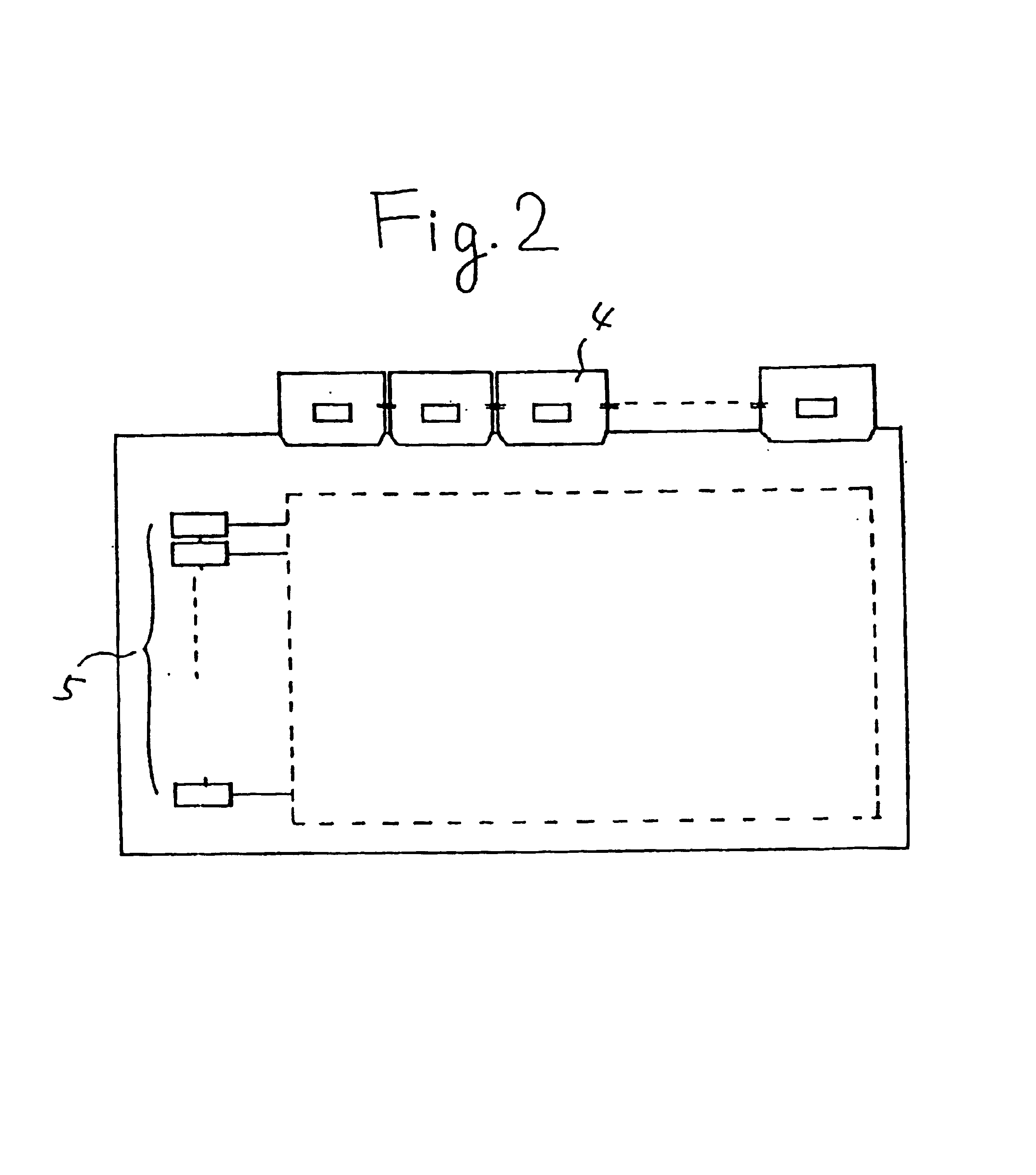
[0044]Referring to FIG. 1, a liquid crystal display device having an m×n circuit structure is described. In FIG. 2 is also given the outer appearance of the liquid crystal display device. In FIG. 1, a shift resister circuit portion 1 (a means for supplying a signal to a wiring of the X direction) being connected to a wiring of the X direction is solely fabricated as TFTs 5 in a similar manner as an active device provided to a pixel 6, and a peripheral circuit portion (a means for supplying a signal to a wiring of the Y direction) connected to a wiring of the Y direction is provided as ICs 4 which is connected to the substrate by TAB. The thin film transistors provided in the pixel 6 as the active device and the thin film transistors 5 constituting the shift resister circuit portion 1 are provided on a single substrate.
[0045]The actual arrangement of the electrodes and the like corresponding to this circuit structure is shown in FIG. 6. In FIG. 6, however, the structure is simplified...
example 2
[0070]In FIG. 7 is given a schematic view of a liquid crystal display device according to another embodiment of the present invention. The basic circuits and the like are the same as those employed in the liquid crystal display device described in Example 1. Referring to FIG. 7, the peripheral circuit connected to the wirings for the Y direction is constructed with ICs 4, and the ICs 4 are directly provided on the substrate by a COG method.
[0071]The pad electrodes of the ICs 4 can be connected with the wirings of the Y direction at a narrower interval by the use of a COG method instead of the TAB method. Thus, the process of the present example enables a finer display pixel design. Furthermore, since the ICs are provided on the substrate, the total volume of the display device remains almost unchanged to give a thinner liquid crystal display device.
example 3
[0072]Referring to FIG. 8, a liquid crystal display device having an m×n circuit structure is described below. Among the peripheral circuit portions (a means for supplying a signal to wirings of the X direction) connected to the wirings of the X direction, only an analog switch array circuit portion 1 is fabricated as TFTs in the same process as that used for fabricating the active device provided to a pixel 6. Furthermore, only an analog switch array circuit portion 2 in the peripheral circuit portion (a means for supplying a signal to wirings of the Y direction) connected to the wirings of the Y direction is also fabricated as TFTs, while providing the rest of the egg peripheral circuit portion by making them into ICs 4 having connected to a substrate using a COG method. The peripheral circuit portion provided as TFTs is in a CTFT structure (complementary structure) similar to the active device established to the pixels.
[0073]In FIG. 6 is provided the actual arrangement of the ele...
PUM
 Abstract
Description
Claims
Application Information
 - R&D
- Intellectual Property
- Life Sciences
- Materials
- Tech Scout
- Unparalleled Data Quality
- Higher Quality Content
- 60% Fewer Hallucinations
Browse by: Latest US Patents, China's latest patents, Technical Efficacy Thesaurus, Application Domain, Technology Topic, Popular Technical Reports.
© 2025 PatSnap. All rights reserved.Legal|Privacy policy|Modern Slavery Act Transparency Statement|Sitemap|About US| Contact US: help@patsnap.com


