Magnetic head, method for producing same, and magnetic recording and/or reproducing system

a technology of magnetic head and head, which is applied in the field of magnetic head and a method for producing the same, and magnetic recording and/or reproducing system, can solve the problems of low reproducing efficiency, inability to obtain a great output, and inability to use magnetic head as a high-density magnetic head, etc., and achieves high efficiency

Inactive Publication Date: 2006-09-05
KK TOSHIBA
View PDF26 Cites 3 Cited by
  • Summary
  • Abstract
  • Description
  • Claims
  • Application Information

AI Technical Summary

Benefits of technology

[0014]It is therefore an object of the present invention to eliminate the aforementioned problems and to provide a magnetic head capable of recording or reproducing with a high efficiency even in the case of a shorter magnetic path length and a shorter wavelength signal, a method for producing the same, and a magnetic recording and / or reproducing system using the same.
[0031]According to the magnetic head with the above described construction according to the first aspect of the present invention, the magnetic gap is formed so as to meet the above described relational expressions, so that it is possible to enhance the reproducing efficiency even in the case of a shorter magnetic path length and a shorter wavelength signal. In addition, it is possible to decrease the length of the magnetic gap on the side of the recording medium, so that it is possible to enhance the resolution.
[0032]According to the magnetic recording head with the above described construction according to the second aspect of the present invention, it is possible to decrease the height of one of the magnetic bodies having the protruding portion, i.e., the distance between the surface of the protruding portion facing the recording medium and the rear surfaces, so that it is possible to decrease the magnetic path length and to greatly improve the recording efficiency. In addition, the protruding portion has the shape tapered off toward the medium facing surface, it is possible to further improve the efficiency when shorter wavelength signals are recorded.
[0033]According to the magnetic reproducing head with the above described construction according to the third aspect of the present invention, it is possible to decrease the height of one of the magnetic bodies having the protruding portion, i.e., the distance between the surface of the protruding portion facing the recording medium and the rear surfaces, so that it is possible to decrease the magnetic path length and to greatly improve the recording efficiency. In addition, the protruding portion has the shape tapered off toward the medium facing surface, it is possible to further improve the efficiency when shorter wavelength signals are recorded.
[0034]According to the magnetic head producing method with the above described construction according to the fourth aspect of the present invention, the beam is applied to the rear plane of the magnetic body and the hole is formed to extend from the rear plane to the principal plane and the magnetic gap is formed in the hole. Thus, it is possible to form a desired magnetic gap, the length of which is small on the side of the principal plane and continuously varies toward the rear plane, and it is possible to decrease the magnetic path length as small as possible, so that it is possible to obtain a magnetic head capable of efficiently carrying out a reproducing operation even in the case of a shorter wavelength signal.
[0035]According to the magnetic head producing method with the above described construction according to the fifth aspect of the present invention, the focused ion beam is used for forming the first and second trenches in the insulating film, and the first and second trenches are filled with the magnetic substance to form the pair of magnetic bodies. Thus, it is possible to obtain the pair of magnetic bodies having desired shapes, and it is possible to decrease the magnetic path length, so that it is possible to obtain a magnetic head having a greatly improved efficiency when shorter wavelength signals are recorded.

Problems solved by technology

This magnetic head can not be used as a high-density magnetic head since it has a low reproducing efficiency or a bad reproducing resolution although it is suited to decrease the magnetic path length.
That is, when the magnetic gap length G is small, most of magnetic fluxes from the medium flow into the magnetic gap, and only part of magnetic fluxes flow into the magnetoresistance effect element, so that it is not possible to obtain a great output.
On the other hand, when the magnetic gap length is great, the line resolution is extremely bad, so that the magnetic head is not worth being used as a tip magnetic head for high density.

Method used


Image

  • Magnetic head, method for producing same, and magnetic recording and/or reproducing system
  • Magnetic head, method for producing same, and magnetic recording and/or reproducing system
  • Magnetic head, method for producing same, and magnetic recording and/or reproducing system

Examples


first preferred embodiment

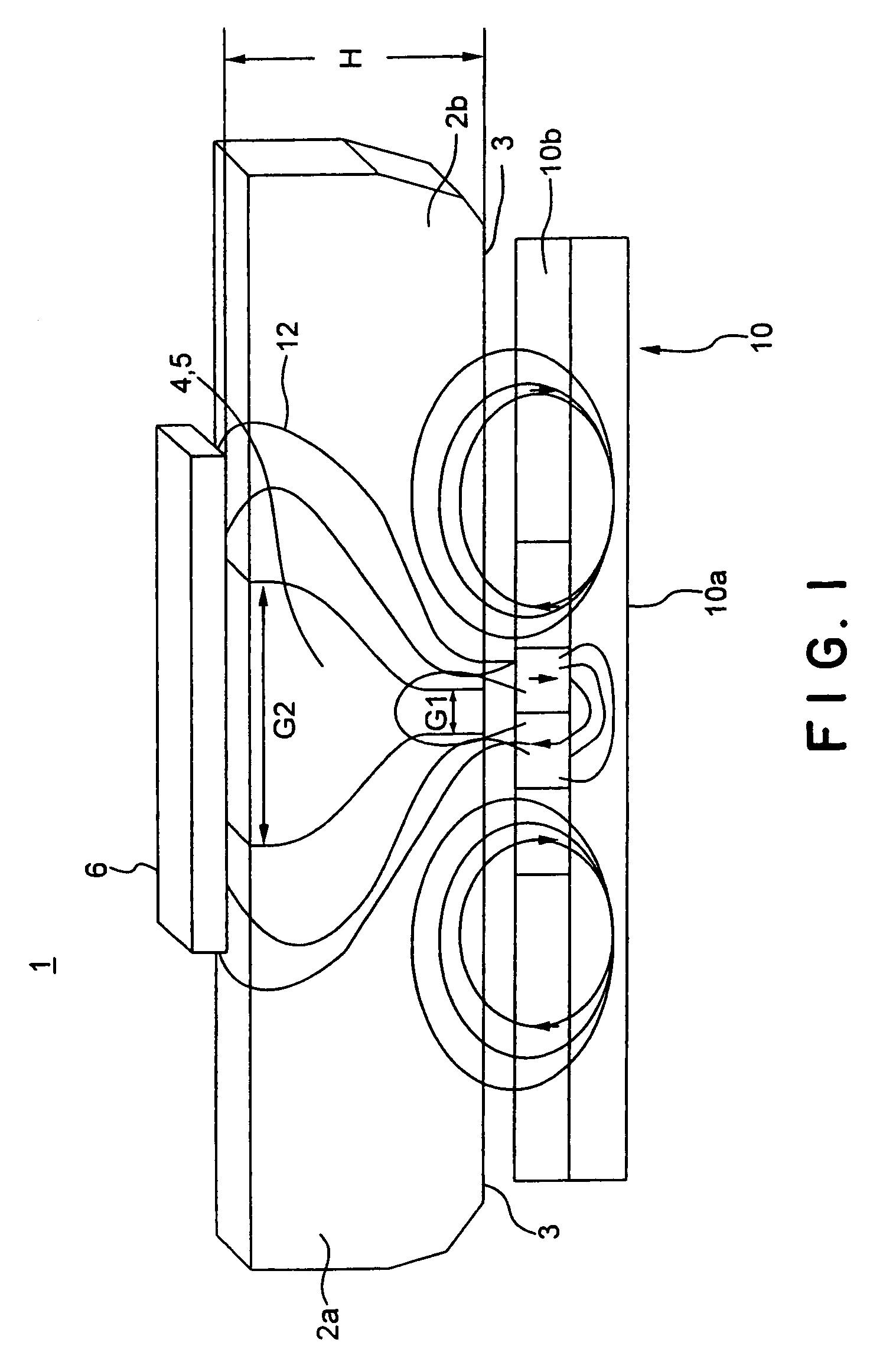
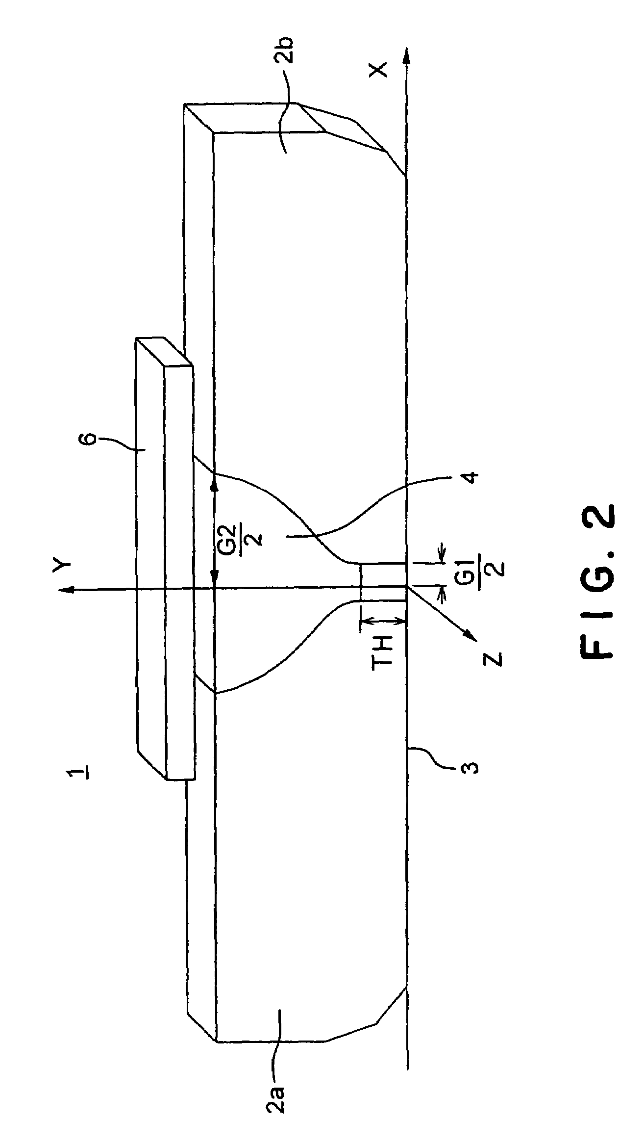
[0063]The construction of the first preferred embodiment of a magnetic head according to the present invention is shown in FIG. 1. The magnetic head 1 in the first preferred embodiment comprises a pair of magnetic substance portions 2a and 2b of a magnetically soft substance having a thickness of, e.g., about 200 nm, a recording coil 5, and a magnetoresistance effect element 6, e.g., 300 nm square. The principal plane 3 of the pair of magnetic substance portions 2a and 2b is arranged so as to be parallel to a recording medium 10. That is, the principal plane 3 serves as a medium facing surface. Furthermore, the recording medium 10 is a vertical recording medium to be formed so that a medium layer 10b on which signals are recorded is formed on a magnetically soft substance film 10a.

[0064]The pair of magnetic substance portions 2a and 2b are arranged so as to be spaced from each other by a magnetic gap 4. This magnetic gap 4 is constructed so as to have a relatively small length G1 o...

second preferred embodiment

[0084]The construction of the second preferred embodiment of a magnetic head according to the present invention is shown in FIG. 8. In this preferred embodiment, a magnetic head 30 is a recording head, and is provided with a magnetic substance portion 7 directly on a pair of magnetic substance portions 2a and 2b and a recording coil 5 so as to straddle the recording coil 5 in place of the magnetoresistance effect element 6 of the magnetic head 1 in the first preferred embodiment shown in FIG. 1.

[0085]In this preferred embodiment, since the magnetic substance portion 7 is provided in place of the magnetoresistance effect element 6, it is possible to form a more smooth magnetic path than that in the first preferred embodiment, and it is possible to further improve the efficiency in a recording operation with a shorter wavelength, so that it is possible to carry out a high-density recording operation.

[0086]Referring to FIG. 9, a method for producing the magnetic head 30 in this preferr...

third preferred embodiment

[0090]The construction of the third preferred embodiment of a magnetic head according to the present invention is sown in FIG. 11. In this third preferred embodiment, a magnetic head 32 is a recording magnetic head, and comprises a pair of magnetic substance portions 2c and 2d of magnetically soft substances, a recording coil 5 and a magnetic substance 7.

[0091]A magnetic gap is provided between the magnetic substance portions 2c and 2d, and the recording coil 5 is provided so as to be filled in the magnetic gap. Furthermore, the length of the magnetic gap may be constant unlike the first and second preferred embodiments. The magnetic substance portion 2d is a main pole serving to record information on a recording medium 10, and has a protruding portion 2d1 having a shape converging toward a medium facing surface. The protruding portion 2d1 also has a shape converging toward the medium facing surface 3 from the side of the recording coil 5. The magnetic substance 7 is formed directly...


PUM

PropertyMeasurementUnit
magnetic path lengthaaaaaaaaaa

Abstract

A method for producing a magnetic head, including the steps of forming a magnetic body on a substrate, the magnetic body including a principal plane facing the substrate and a rear plane opposite to the principal plane; applying a beam to the rear plane of the magnetic body and forming a portion defining a hole extending from the rear plane to the principal plane; forming a magnetic gap in the hole; and separating the magnetic body and the magnetic gap from the substrate and forming medium facing surface substantially coplanar with the principal plane.

Description

CROSS REFERENCE TO RELATED APPLICATION[0001]This application claims benefit of priority under 35USC § 119 to Japanese Patent Application No. 2000-95082, filed on Mar. 30, 2000, the contents of which are incorporated by reference herein.BACKGROUND OF THE INVENTION[0002]1. Field of the Invention[0003]The present invention relates generally to a magnetic head and a method for producing the same, and magnetic recording and / or reproducing system.[0004]2. Description of Related Art[0005]It is generally known that the efficiency of a magnetic head is rapidly improved as the magnetic path length of a magnetic circuit decreases. For example, as shown in FIG. 18A, the efficiency is rapidly improved as the magnetic path length decreases to 2 μm (=2000 nm) or less. As shown in FIG. 18B, the magnetic path length means the length of a magnetic circuit passing through a magnetic substance portion 52a, magnetic substance portion 53a, magnetoresistance effect element (e.g., GMR(giant magnetoresistan...

Claims


Application Information

Patent Timeline
Patent Type & Authority Patents(United States)
IPC IPC(8): G11B5/127G11B5/187G11B5/00G11B5/23G11B5/31G11B5/39
CPCG11B5/00G11B5/127G11B5/3116G11B5/3925G11B5/1278G11B2005/0002Y10T29/49043Y10T29/49044Y10T29/49067Y10T29/49039Y10T29/49046Y10T29/49055G11B2005/0021G11B5/39
Inventor YODA, HIROAKIOSAWA, YUICHIFUNAYAMA, TOMOMI
Owner KK TOSHIBA
Why Eureka
Try Eureka