
Prismatic boresighter

a technology of boresighter and spherical body, which is applied in the direction of instruments, weapons, aiming means, etc., can solve the problems of not being able to use other systems, and achieve the effect of improving performan

Active Publication Date: 2006-09-05
OPTICS RES HK
View PDF7 Cites 13 Cited by
  • Summary
  • Abstract
  • Description
  • Claims
  • Application Information

AI Technical Summary

Benefits of technology

[0007]It is the object of this invention to provide a substantially smaller, lightweight and fog-proof collimator system, that has benefits and improved performance over other available systems as described.
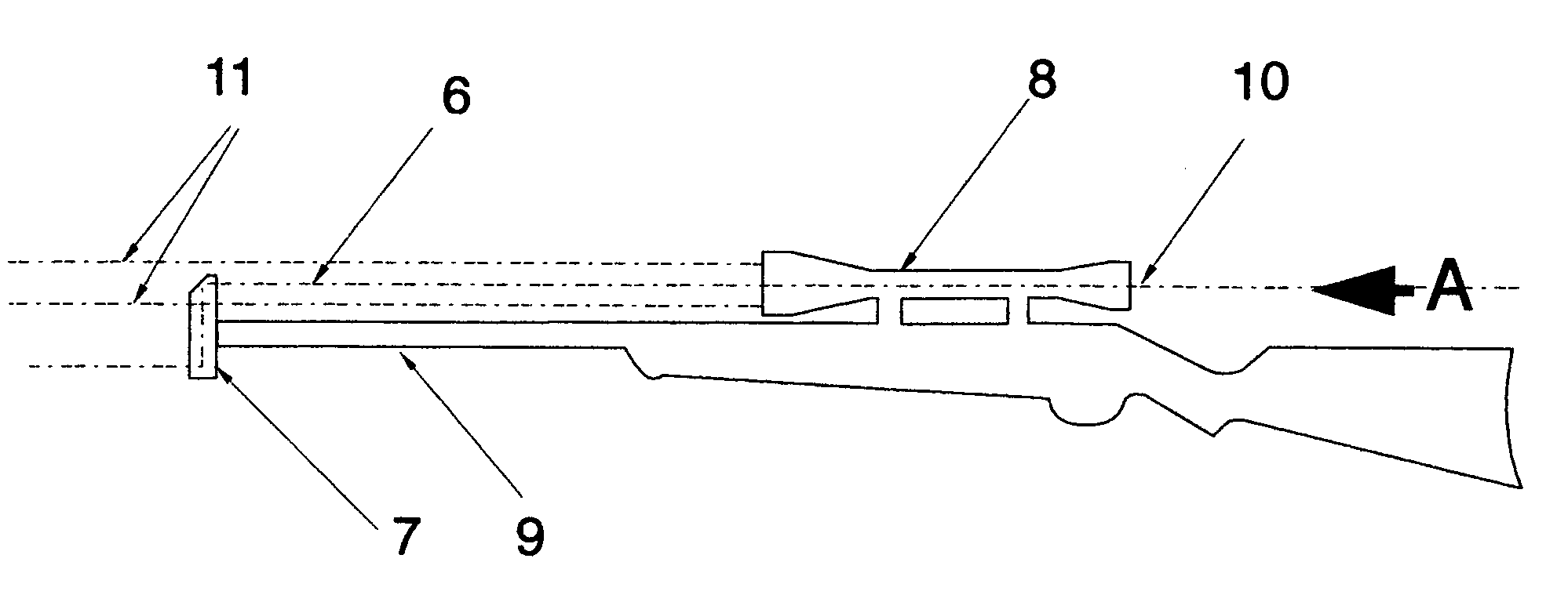
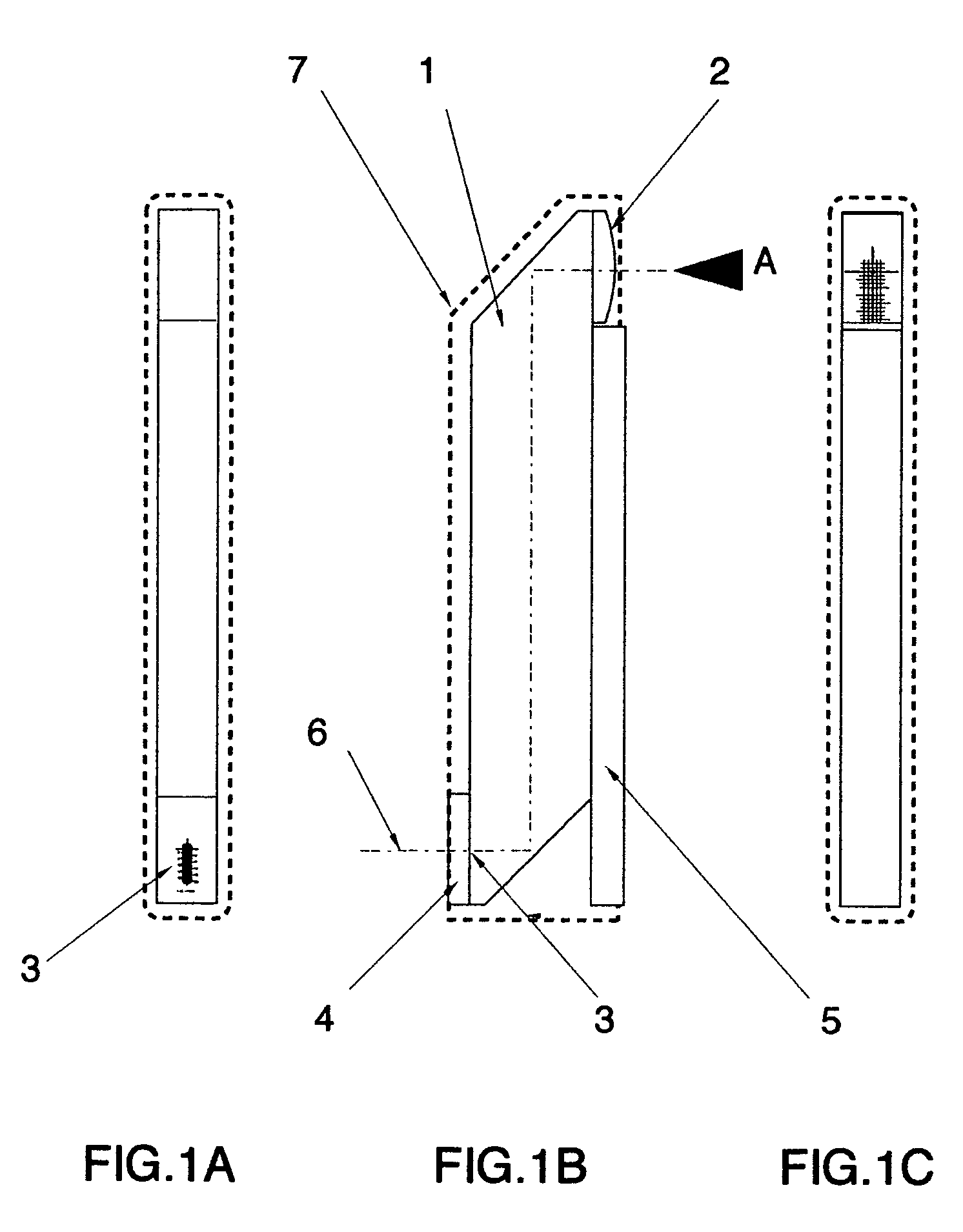
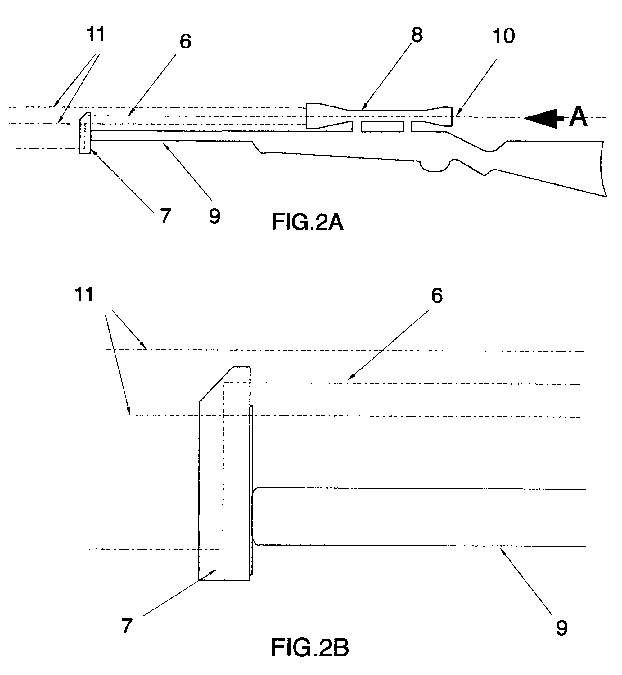
[0008]The present invention is an optical collimator device for use in aligning a riflescope with the bore of a rifle. The construction is designed with a prismatic element between the magnifying lens and the reticule. It uses the prismatic element to fold the optical path length to make the system compact, and uses a magnetic strip to attach the collimator to the muzzle of a rifle barrel, allowing vertical height adjustment for various sight designs.
[0009]The optical design provides a much smaller lens and an increased focal length to lens aperture ratio, this ratio is typically greater than 6, where as alternative systems use a ratio of typically 3, so that when the design is used with a magnifying riflescope, the design allows the simultaneous viewing of the target and the reticule pattern in conjunction with the riflescope cross wires.
[0010]The ability to see the target with the reticule pattern image is of great benefit to the user, as the point of impact on the target can be seen with the reticule pattern, and allows the sight cross wires to be adjusted to the point of impact, while the reticule pattern is still centred on the target. This allows one shot zeroing, which is not possible with other systems.
[0012]The use of a much smaller aperture lens (approximately one quarter of a standard design) with double the normal focal length gives better optical performance, as the placement of the reticule at the lens focal plane is not as critical as other systems, and spherical and chromatic aberrations are dramatically reduced, and the use of an achromatic lens design, which is a standard requirement on other systems, is no longer required. This dramatically reduces production costs.

Problems solved by technology

This allows one shot zeroing, which is not possible with other systems.

Method used


Image

  • Prismatic boresighter
  • Prismatic boresighter
  • Prismatic boresighter

Examples


Embodiment Construction

[0020]According to the present invention there is provided an optical collimator device with a reticule pattern placed optically at infinity, characterised in that a magnifying optical element is placed in front of it along the optical path to enable the reticule pattern to be seen with the naked eye.

[0021]The optical path between the reticule pattern and the magnifying optic is transmitted through a block of optically transparent material forming a rhomboid prism. The optical path is aligned by internal reflecting surfaces at two positions so as to fold the optical path, the longer part of the optical path is arranged to be perpendicular to the barrel of the rifle forming a compact arrangement.

[0022]There is also provided a magnetic strip that enables the mounting of the device onto the muzzle of a barrel, permitting vertical adjustment of the collimator. The magnetic strip is directly mounted to the long section the prism for rigidity and compactness.

[0023]FIG. 1B shows the glass ...


PUM


Abstract

An optical collimator device, for use in aligning a riflescope with the bore of the rifle, is formed using a small aperture lens for viewing a reticule through a prismatic assembly. The collimator is magnetically attached to the muzzle of the rifle, and when a target is viewed through the riflescope the image of the reticule and the riflescope cross wires are seen simultaneously with the image of the target.

Description

BACKGROUND TO THE INVENTION[0001]The present invention relates to bore sight collimators that are used to align a sight with the bore of a gun.[0002]At present an optical boresighter uses an optical collimating system consisting of a lens that is optically aligned with a reticule marked on a glass plate, positioned at the focal plane of the lens. The lens and the reticule plate are mounted at either end of a housing.[0003]The alignment of the collimator housing to the bore of the gun is achieved by use of a close fitting pin inserted into the end of the barrel, to which the collimator housing is clamped. Alternatively a magnetic strip is built into to the collimator housing, such that the collimator can be attached to the end of a gun barrel magnetically. The end of the barrel is by necessity, square with the bore, and this gives the necessary alignment.[0004]In both these systems the optical element of the collimator is relatively large, it is similar to, or larger in size, to the ...

Claims


Application Information

Patent Timeline
Patent Type & Authority Patents(United States)
IPC IPC(8): F41G3/00F41G1/54
CPCF41G1/54
Inventor PAIGE, CLIVE RAWLINSON
Owner OPTICS RES HK
Learn More