
Plasma production device and method and RF driver circuit with adjustable duty cycle

a technology of a production device and a duty cycle, applied in the direction of individual energised antenna arrays, plasma techniques, coatings, etc., can solve the problems of affecting the antenna loading, affecting the accuracy of tuning these components, and progressive electrical breakdown, so as to reduce circuit complexity, eliminate a source of failure, and reduce output impedance

Inactive Publication Date: 2006-09-05
LAM RES CORP
View PDF43 Cites 35 Cited by
  • Summary
  • Abstract
  • Description
  • Claims
  • Application Information

AI Technical Summary

Benefits of technology

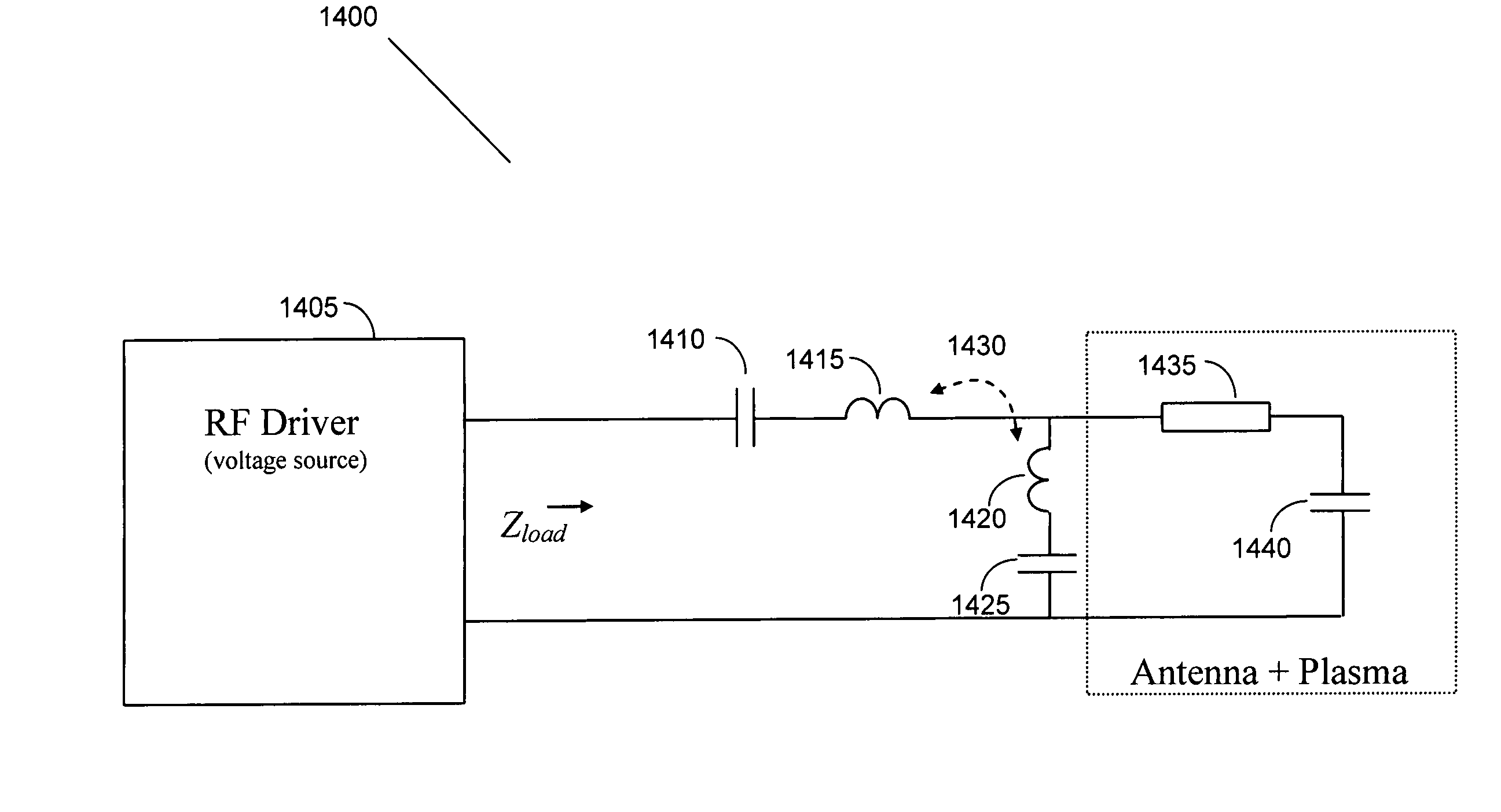
[0028]Instead of dynamic impedance matching network, a reactive network couples the RF power source to the antenna-plasma combination. The reactive network is selected so that at least a first plasma impedance value, a substantially resistive load is presented to the RF power source. Further at a second plasma impedance value, preferably, selected so as to significantly cover the expected dynamic plasma reactance range, the reactance seen by the RF power source is about the same as that of the RF power source itself. Thus, disclosed herein are a method of designing a reactive circuit to eliminate the need for a dynamic matching circuit between a plasma and a RF power source. Also disclosed is a reactive circuit suitable for a plasma generator operating at about 13.56 MHz. The described method is also applicable for designing reactive circuits for many frequencies other than 13.56 MHz.
[0036]Another advantage of the disclosed system is that the elimination of the dynamic matching network allows an “instant-on” type of operation for the plasma source. This characteristic can be used to provide an additional control for the process being used. In particular, it is possible to modulate the amplitude of the RF power generating the plasma, between two (or more) levels such as 30% and 100%, or in a fully on-off manner (0% to 100%). This modulation can occur rapidly, e.g. at a frequency of several kilohertz, and can accomplish several purposes. For instance, the average RF power can be reduced with a consequent reduction in average plasma density. The “instant-on” operation can generate plasma with an average RF input power of as little as 5 W in a volume of 50 liters.

Problems solved by technology

In addition, the amplitude of the RF drive waveform itself affects the plasma temperature and density, which in turn also affects the antenna loading.
Not surprisingly, accurate tuning of these components is often a difficult process.
This leads to a further increase in the induced currents, resulting in the progressive electrical breakdown and substantial ionization of the gas.
However, these designs are relatively complex often requiring custom components that increase the cost of system acquisition and maintenance.
Moreover, not all of the designs are suitable for efficient generation of the helicon mode, which is a preferred mode disclosed herein.
In power amplification, an important concern is the amount of power wasted as heat, since heat sinks must be provided to dissipate the heat and, in turn, increase the size of devices using an inefficient amplifier.
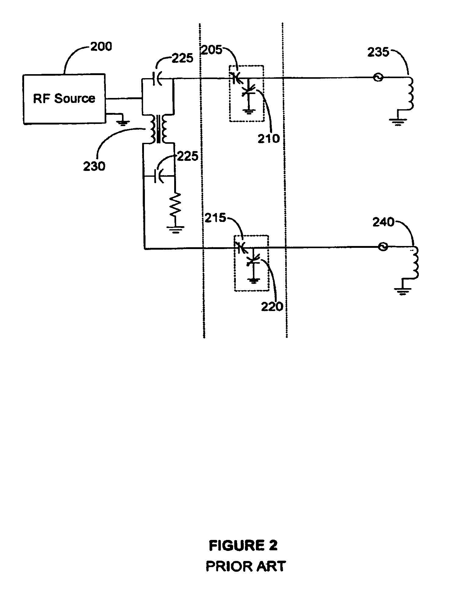
These matching networks add to the complexity for operation with a switched mode power supply rather than eliminate the dynamic matching network.
Such a matching load network is also not very frequency agile since it depends on strong selection for a narrow frequency band about the fundamental.
Overwhelming the plasma inductance with a sufficiently high power driver results in compromising efficiency to some extent.
The problems faced in an efficient plasma generator design include the need for a low maintenance and easily configured antenna, the elimination of expensive dynamic matching networks for directly coupling the RF power source to the non-linear dynamic impedance presented by a plasma, and the need for RF power sources that can be efficiently modulated and are frequency agile.

Method used


Image

  • Plasma production device and method and RF driver circuit with adjustable duty cycle
  • Plasma production device and method and RF driver circuit with adjustable duty cycle
  • Plasma production device and method and RF driver circuit with adjustable duty cycle

Examples


Embodiment Construction

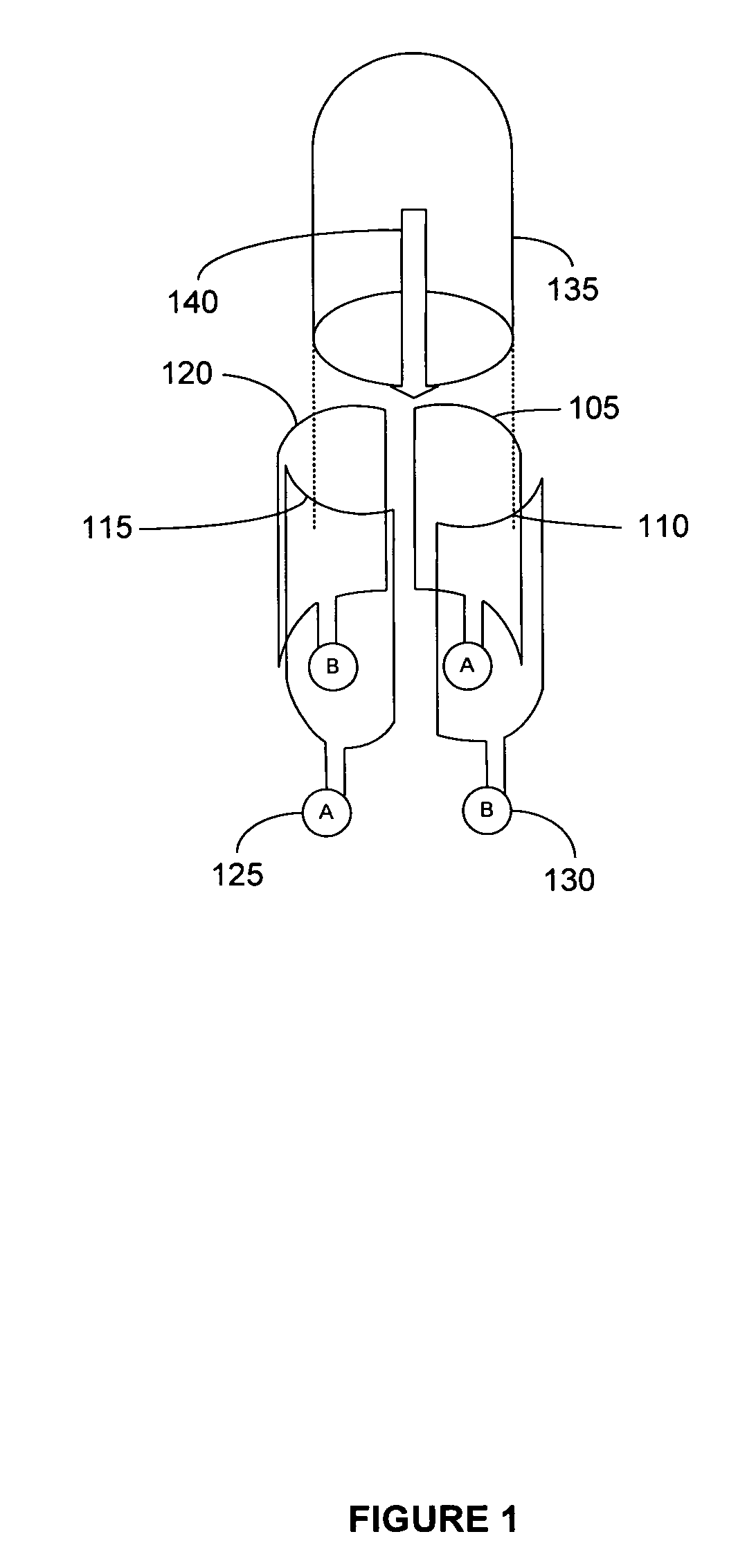
[0054]Turning to the figures, FIG. 1 illustrates a plasma source chamber with two sets of antenna elements. The antenna design includes two orthogonal single- or multi-turn loop elements 105, 110, 115, and 120, arranged about a common axis. The antenna elements 105, 110, 115, and 120 are each driven by RF power sources, A 125 or B 130 as shown. Each antenna loop may be coupled to the same RF power source with a phase splitter, or to distinct RF power sources, to drive the antenna elements in quadrature. Preferably the loops in the antenna are constructed from eight (8) gauge teflon coated wire although bare copper wire or other conductors may also be used.

[0055]FIG. 1 shows two orthogonal sets of two-element Helmholtz-coil-like loop antennas, with loop elements 105 and 115 in one set and loop elements 110 and 120 in the second set. The loop elements are wrapped azimuthally around an insulating cylinder 135 such that the magnetic fields that are produced when a current is passed thro...


PUM

PropertyMeasurementUnit
plasma resistanceaaaaaaaaaa

Abstract

A reactive circuit is disclosed as part of a method and system for generating high density plasma that does not require the use of a dynamic matching network for directly driving a plasma exhibiting a dynamic impedance. The reactive network is designed to provide a small total reactance when the plasma reactance is at a first plasma reactance and presents a reactance that does not exceed a specified limit at a second plasma reactance. The first and second plasma reactance span a substantially fraction of an expected dynamic plasma reactance range. The first and second plasma reactance values may, for example, correspond to a high expected plasma reactance limit and a low expected plasma reactance limit respectively or the first plasma reactance may correspond to an average expected plasma reactance.

Description

REFERENCE TO RELATED APPLICATIONS[0001]This application claims priority to U.S. Provisional Patent Application No. 60 / 480,338 filed on Jun. 19, 2003 under 35 U.S.C. §119, and is a continuation-in-part of U.S. patent application Ser. No. 10 / 419,052 filed on Apr. 17, 2003, which is a continuation-in-part of U.S. patent application Ser. No. 10 / 268,053 filed on Oct. 9, 2002, which claims the benefit under 35 U.S.C. §119 of priority to U.S. Provisional Patent Application No. 60 / 328,249 filed on Oct. 9, 2001, all of which are incorporated herein in their entirety by reference.FIELD OF THE INVENTION[0002]The present invention relates generally to the design and implementation of a plasma generation system. More particularly, it relates to radio frequency amplifiers, antennas and effective circuit connections for interfacing the amplifiers and antennas for generating plasma.BACKGROUND OF THE INVENTION[0003]Plasma is generally considered to be one of the four states of matter, the others bei...

Claims


Application Information

Patent Timeline
Patent Type & Authority Patents(United States)
IPC IPC(8): C23C16/00C23F1/02H01J37/32H01Q1/26H01Q7/00H01Q21/20H05H1/46
CPCH01J37/32082H01J37/321H01J37/32128H01J37/32174H05H1/46H01Q1/26H01Q7/00H01Q21/205H01J37/32522
Inventor PRIBYL, PATRICK
Owner LAM RES CORP
Learn More