Handling such a bulky product without any compression is clearly impractical, particularly from an economic point of view.
However, compression cannot be allowed to damage the product to the point that it does not recover its nominal thickness and performance levels after unpacking.
Lack of thickness and
performance recovery directly translate into some loss in product utility and value, defeating the purpose of the exercise.
These machines typically overcompress the leading portion of the
blanket, causing some loss in
thermal insulation value for this portion due to lack of product thickness
recovery after unpacking.
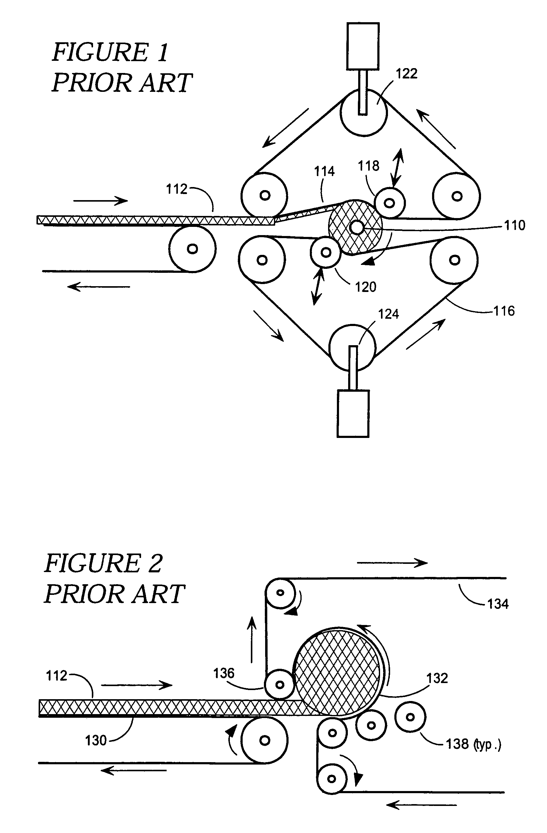
While this design operates more quickly and efficiently than that of the '696 patent, it still suffers from the deficiency of over-compressing the
leading edge of the material being rolled.
While roll-up machines of the single-belt “free-loop” design offer some advantages over mandrel-based designs, they still suffer from several major operational deficiencies.
As explained in U.S. Pat. No. 6,321,507, the conventional, single-belt “free-loop” design, with a fixed belt width, has a limited ability to efficiently
package compressible materials of various widths.
Telescoping complicates the wrapping of the roll product with a
sheet material (such as a
plastic film) as overall, the roll is now longer than it should be.
As well, the ends of the roll are conical instead of flat, making stacking in a warehouse or storage facility difficult.
While the surplus material may be recycled as
loose fill insulation or admix, this process is both an inconvenience and economically inefficient.
This is a complicated approach to the telescoping problem, and of course, does nothing to address other problems with the “free-loop” designs.
These other problems include the following:1. dealing with tremendous slack on the continuous belt when the rolled material is released (i.e. slack is the difference between the
circular segment of belt encircling the roll, and the corresponding straight-
line length of belt between the rollers, after the finished roll has been ejected).
This slack often causes the belt to leave its guides; and2. lack of control over the actual shape and quality of the roll.
As the material typically takes on an irregular and inconsistent cross-section, handling and storage are difficult and inefficient.
As well, the
irregular shape will result in uneven compression which may damage the compressible material.
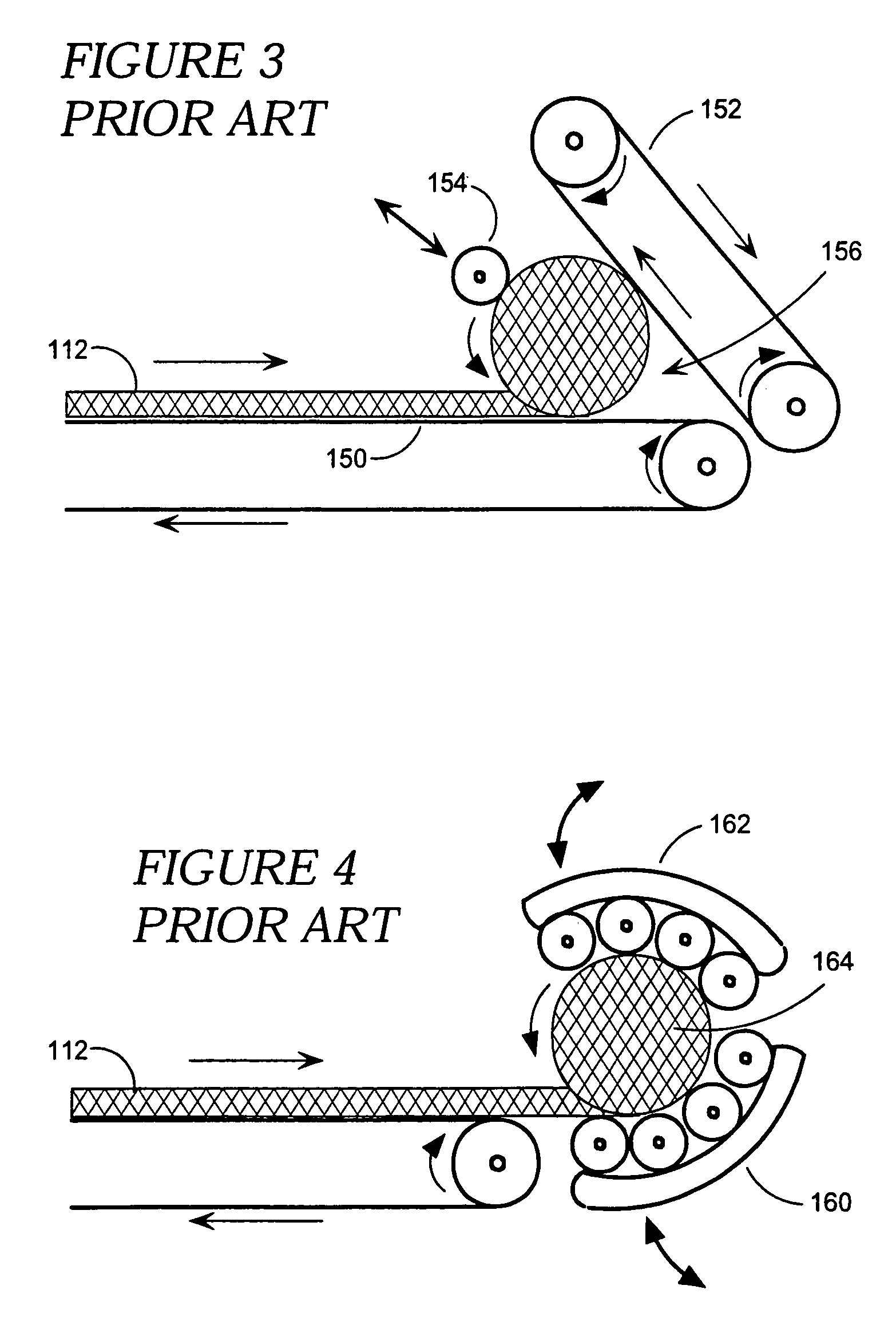
This does not change the basic fact, however, that the compressive force can only be applied to a limited area, instead of being distributed more or less uniformly over the whole roll circumference, as in the single-belt, “free-loop” roll-up machines.
If one squeezes too much, in an attempt to end up with a tight roll with a high overall
compression ratio, fibre breakage and / or binder bond loss is likely to occur in the compression zones, resulting in poor thickness
recovery after unrolling.
This cycle of compression and de-compression is repeated many times as the roll is formed, the repetitive loading damaging fibres and causing binder fatigue.
It is not that convenient or economical to have this two-stage operation; quite often the process is not
fully automatic and requires additional manpower compared to one-step processes.
This second-stage compression also causes further damage to the material because the material is in a fixed roll when the second compression is applied.
This two-stage technique is slow, requires two machines, requires manual labour between the two stages, and damages the compressed material because of the tight compressed turns in the material, formed during the second stage.
There are a number of major problems with two-belt roll-up machines in general.
For example:1. with a two-belt design it is quite difficult to start the formation of a new roll.
Thus, the two-belt roll-up
machine cannot start rolling the compressible material in a neat and uniform way.
This slack can cause the belts to leave their guides during the operational cycle, so many designs used take up cylinders to absorb this slack.
The more slack that has to be absorbed, the longer the travel of the take up cylinder
system.A more detailed discussion of slack is described hereinafter;2. the two-belt designs known in the art also require a very quick and drastic change in the positions of the rollers for a speedy ejection of the roll of product; and3. also similar to the “free loop” systems, two belt roll up machines do not maintain cross-section symmetry very well.
This often results in geometrical
distortion of the completed roll, commonly known as coning or telescoping.
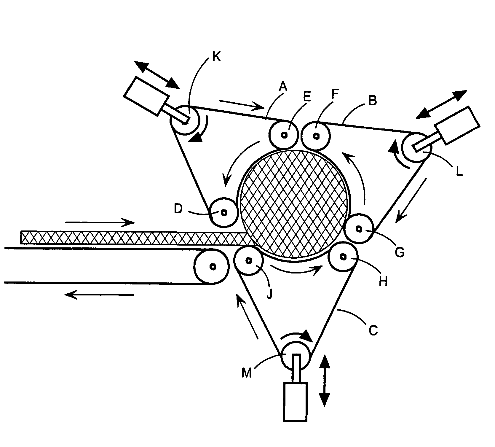
There is therefore a need for a high-compression roll-up
machine and method of rolling that results in consistent and uniformly shaped rolls, with minium damage to the material being rolled.


