
Apparatus for positioning an occupant of a vehicle

a technology for positioning vehicles and occupants, applied in the direction of seat furniture, vehicle safety belts, armoured vehicles, etc., can solve the problems of commanding officer being hurled out of the vehicle or even crushed, vehicle tilting, transmission of strong shock wave, etc., and achieve the effect of improving the balance of the occupan

Inactive Publication Date: 2006-09-05
SCHROTH SAFETY PRODS
View PDF8 Cites 60 Cited by
  • Summary
  • Abstract
  • Description
  • Claims
  • Application Information

AI Technical Summary

Benefits of technology

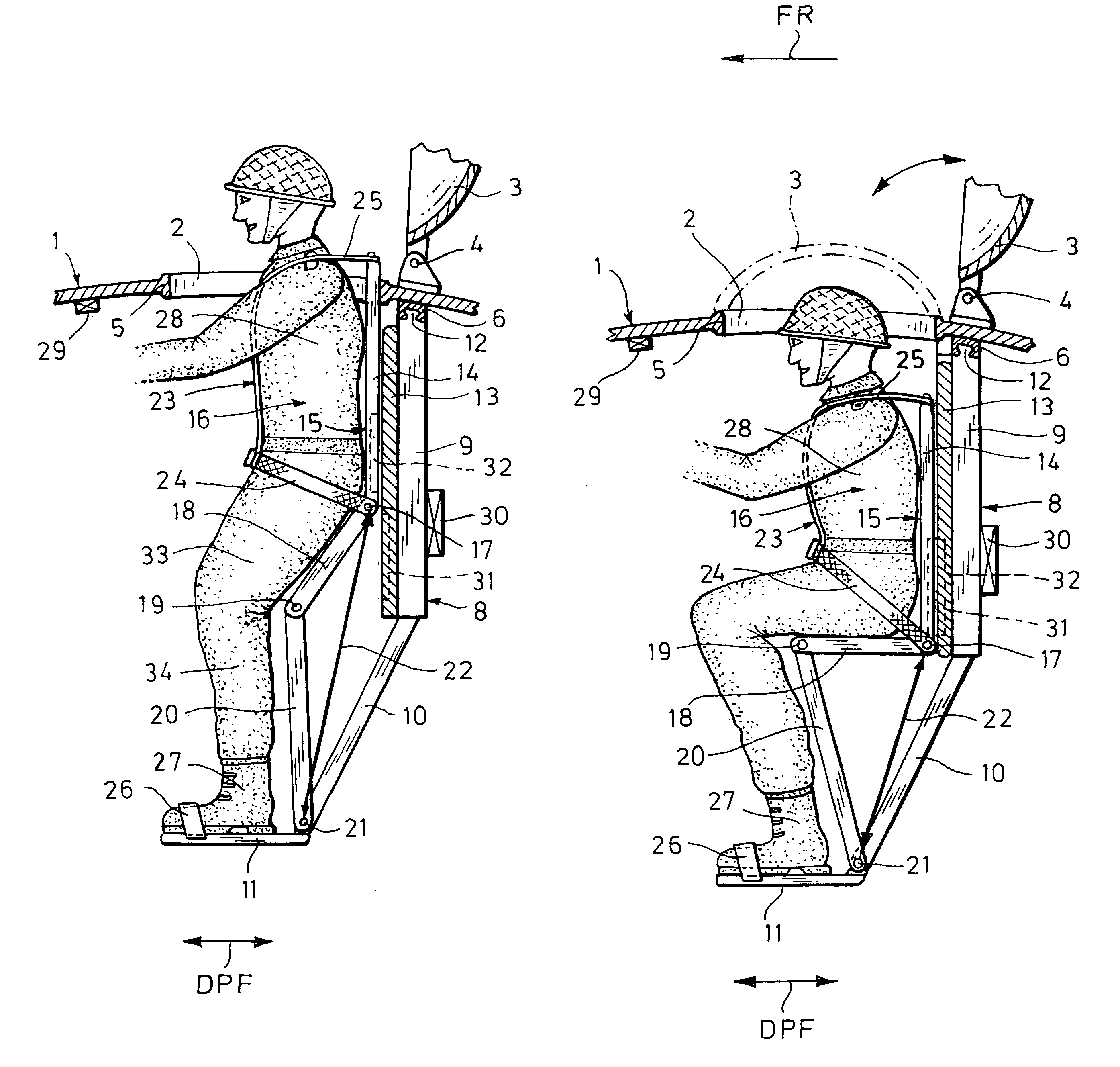
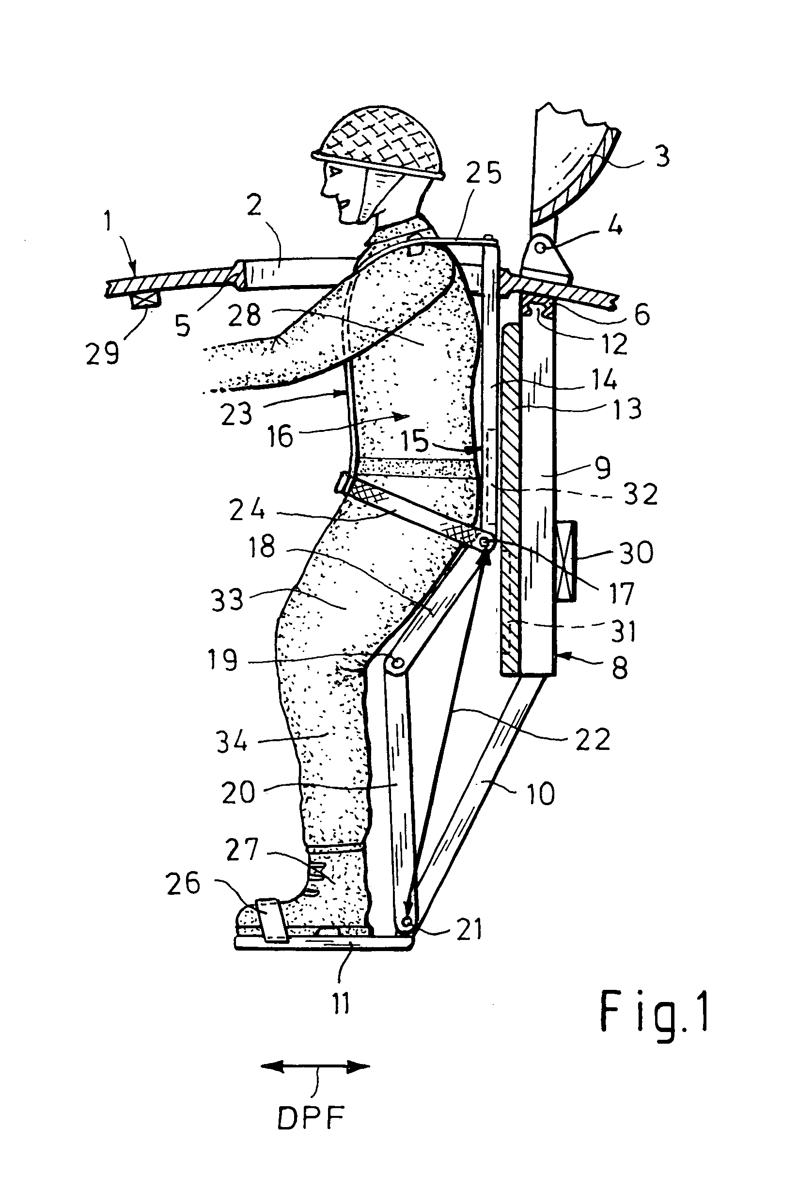
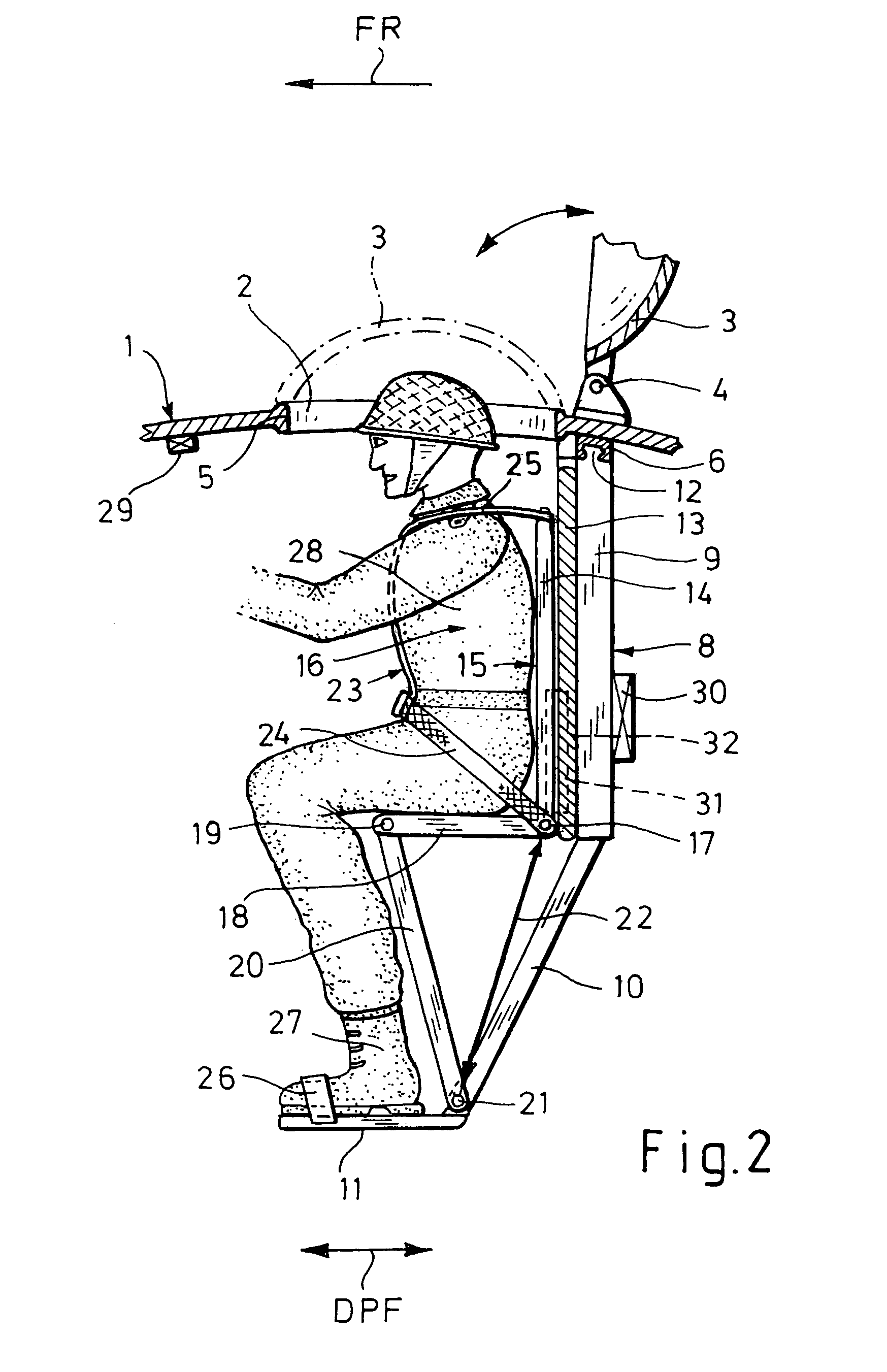
[0010]The present invention resolves prior art problems by providing a carrier frame which is suspended underneath the roof hatch and has a vertical support portion and a horizontal standing area for the commander. The suspended disposition of the carrier frame eliminates a force connection with the vehicle bottom so that shock waves caused, e.g., by a mine explosion are no longer transmitted through. The backrest of the seat assembly is mounted to the vertical support portion and thus can move only in vertical direction. As the backrest is permanently loaded to seek the upper end position, the components of the seat assembly, i.e., backrest, seating area and brace, exhibit in base position a substantially stretched vertical configuration. As a consequence, all occupants of the vehicle are able to easily access or exit the vehicle, when the hatch cover is swung open.
[0027]In order to improve the balance of the occupant, in particular in upright position, the standing area may have a restraining member for securing footwear of the occupants in place. An example of a restraining member includes a strap which secures the footwear against sliding off from the standing area.

Problems solved by technology

However, as the vehicle is exposed in addition to natural movements and braking operations to significant spatial vibrations, especially in off-road terrain, the commander has to protect himself or herself from hitting the upper body against the edge of the hatch by moving the upper body as far out as possible from the hatch and using the hands to hold onto external parts of the vehicle for stabilizing the position.
Rather, the commander will be hurled out of the vehicle or even crushed by the vehicle.
Another dangerous situation for the commander occurs when the vehicle strikes a mine which explodes and then causes the vehicle to tilt.
In addition, a strong shock wave is generated which is transmitted through the bottom-mounted seat into the lower leg and thigh as well as spine of the commander, when the vehicle is caused to significantly accelerate in vertical direction as a consequence of the mine explosion.
Although this approach secures the commander to the seat assembly, there is still the problem that the seat assembly is coupled to the vehicle bottom.
As a result, the commander is forced to follow all motions of the vehicle and thus can be subjected to oftentimes significant accelerating forces.
Moreover, such a seat assembly has the drawback that its entire mass including the weight of the commander buckled thereto must be lifted and lowered.
Lifting must be implemented by mechanical means because vehicles of this type normally are not equipped with a hydraulic system due to combustibility of hydraulic fluid.
When the vehicle rolls over or hits a mine which then explodes, there is not enough time for the mechanic system to respond and move the seat assembly with the commander out of the danger zone in the area of the hatch.
Mechanical lifting of the seat assembly is also disadvantageous because the seat assembly blocks in the upper position the hatch so that the commander, even when unbuckling the safety belt, is unable to stretch in order to leave the vehicle via the hatch with straight legs.
Finally, there is also a risk that the seat assembly jams in the upper position, as a result of hitting a mine and of the resultant significant high accelerations, and then can no longer be moved downwards.
Thus, the hatch is permanently blocked for use as escape route.

Method used


Image

  • Apparatus for positioning an occupant of a vehicle
  • Apparatus for positioning an occupant of a vehicle
  • Apparatus for positioning an occupant of a vehicle

Examples


Embodiment Construction

[0034]Throughout all the Figures, same or corresponding elements are generally indicated by same reference numerals. These depicted embodiments are to be understood as illustrative of the invention and not as limiting in any way. It should also be understood that the drawings are not necessarily to scale and that the embodiments are sometimes illustrated by graphic symbols, phantom lines, diagrammatic representations and fragmentary views. In certain instances, details which are not necessary for an understanding of the present invention or which render other details difficult to perceive may have been omitted.

[0035]Turning now to the drawing, and in particular to FIG. 1, there is shown a schematic vertical section of a positioning apparatus according to the present invention for use by an occupant in an exemplary armored vehicle, generally indicated by reference numeral 1 and shown here only by those parts that are necessary for the understanding of the invention. The armored vehic...


PUM


Abstract

Apparatus for positioning an occupant of a vehicle in an area of a closeable roof hatch includes a carrier frame suspended within a vehicle below the roof hatch and including a vertical support portion and a horizontal standing area connected to the vertical support portion. A seat assembly for the occupant has a backrest which is guided by the vertical support portion for movement in a vertical direction between upper and lower end positions and is spring-biased to seek the upper end position. The seat assembly has a seating area, which is swingably mounted to a lower end of the backrest, and a coupling brace, which has one end swingably mounted to the seating area and another end swingably mounted to the standing area. Connected to the seat assembly is a seat belt for fastening the occupant.

Description

CROSS-REFERENCES TO RELATED APPLICATIONS[0001]This application claims the priority of German Patent Application, Serial No. 103 17 314.5, filed Apr. 14, 2003, pursuant to 35 U.S.C. 119(a)–(d), the disclosure of which is incorporated herein by reference.BACKGROUND OF THE INVENTION[0002]The present invention relates to an apparatus for positioning an occupant of a vehicle in an area of a closeable roof hatch.[0003]Vehicles, in particular armored vehicles used by the military or police, normally accommodate several occupants. One occupant, the so-called commander assumes the task to view the situation around the vehicle and to derive conclusions which may possibly be relayed to the other occupants. To enable the commander to reliably survey the surrounding environment, the vehicle involved here has a roof hatch which can normally be closed by a manually operated hatch cover. If the hatch cover is swung open to clear the hatch, the commander is able to stand in the hatch and to monitor ...

Claims


Application Information

Patent Timeline
IPC IPC(8): A62B35/00B60R22/12B60N2/24B60N2/30B60N2/38B60N2/42F41H7/02
CPCB60N2/24B60N2/3027B60N2/3065B60N2/4242F41H5/223F41H7/046B60N2/38B60N2002/247
Inventor SCHROTH, CARL-JURGEN
Owner SCHROTH SAFETY PRODS
Learn More