Method of determining abnormality of nozzles in imaging apparatus; imaging apparatus; electrooptic device; method of manufacturing electrooptic device; and electronic equipment

a technology of imaging apparatus and abnormal nozzles, which is applied in the manufacture of electrode systems, electric discharge tubes/lamps, instruments, etc., can solve the problems of clogging of ejection nozzles, long operation time, and abnormal ejection nozzles, so as to prevent an erroneous determination and perform an imaging operation efficiently

Active Publication Date: 2006-09-05
KATEEVA
View PDF14 Cites 27 Cited by
  • Summary
  • Abstract
  • Description
  • Claims
  • Application Information

AI Technical Summary

Benefits of technology

[0013]In consideration of the foregoing circumstances, it is an advantage of this invention to provide a method of determining abnormality of nozzles in an imaging apparatus, the imaging apparatus, an electrooptic device, a method of manufacturing the electrooptic device and electronic equipmen

Problems solved by technology

Here, if an imaging operation is halted for a certain amount of time to perform loading/unloading of the workpiece and the like, clogging of the ejection nozzles may be caused by increased viscosity of the function liquid of the liquid droplet ejection heads.
Specifically, even if the function liquid is normally ejected from the ejection nozzles, a determination of abnormal ejection is made, that is, the ejection nozzles may be d

Method used


Image

  • Method of determining abnormality of nozzles in imaging apparatus; imaging apparatus; electrooptic device; method of manufacturing electrooptic device; and electronic equipment
  • Method of determining abnormality of nozzles in imaging apparatus; imaging apparatus; electrooptic device; method of manufacturing electrooptic device; and electronic equipment
  • Method of determining abnormality of nozzles in imaging apparatus; imaging apparatus; electrooptic device; method of manufacturing electrooptic device; and electronic equipment

Examples


Embodiment Construction

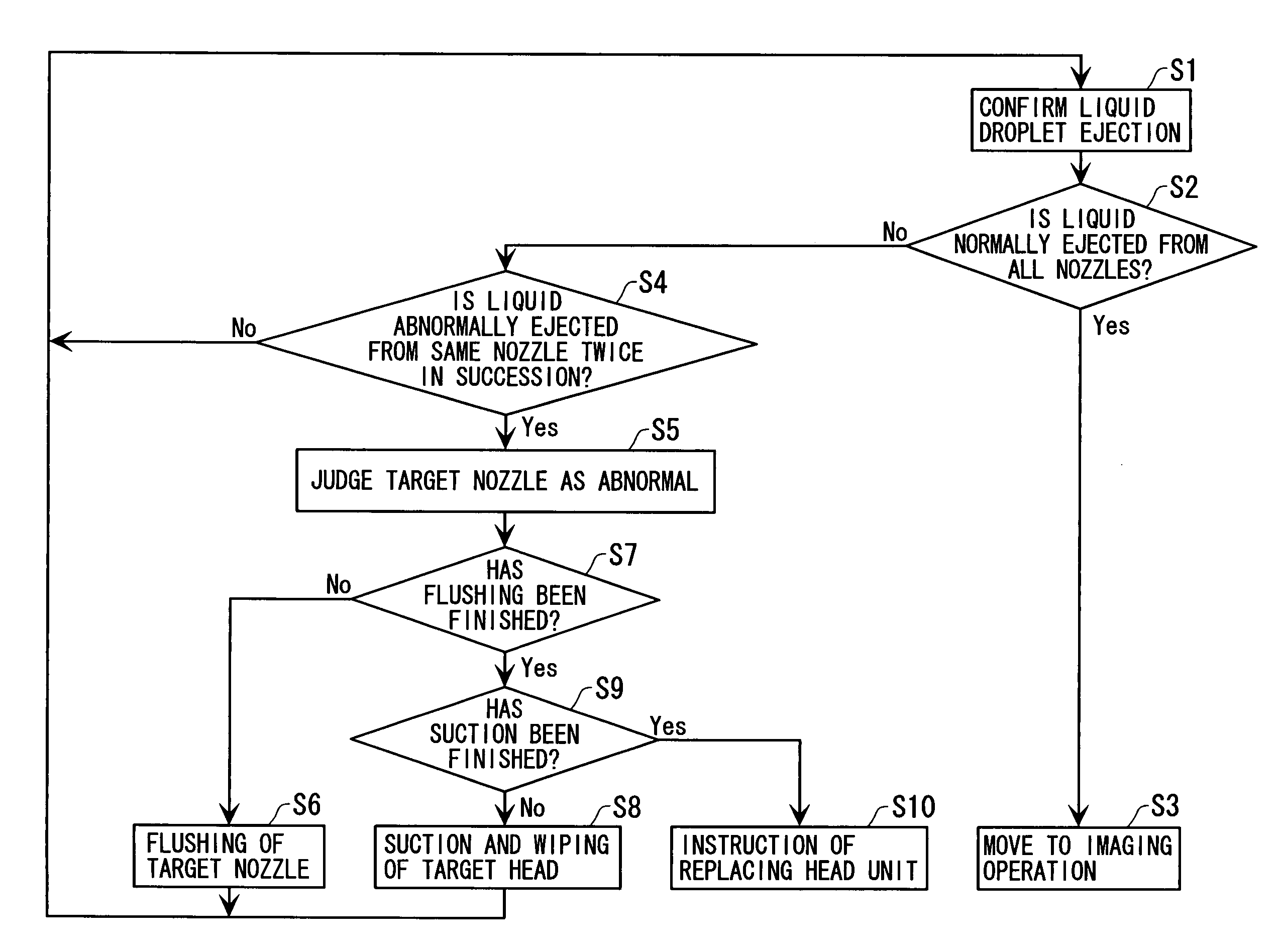
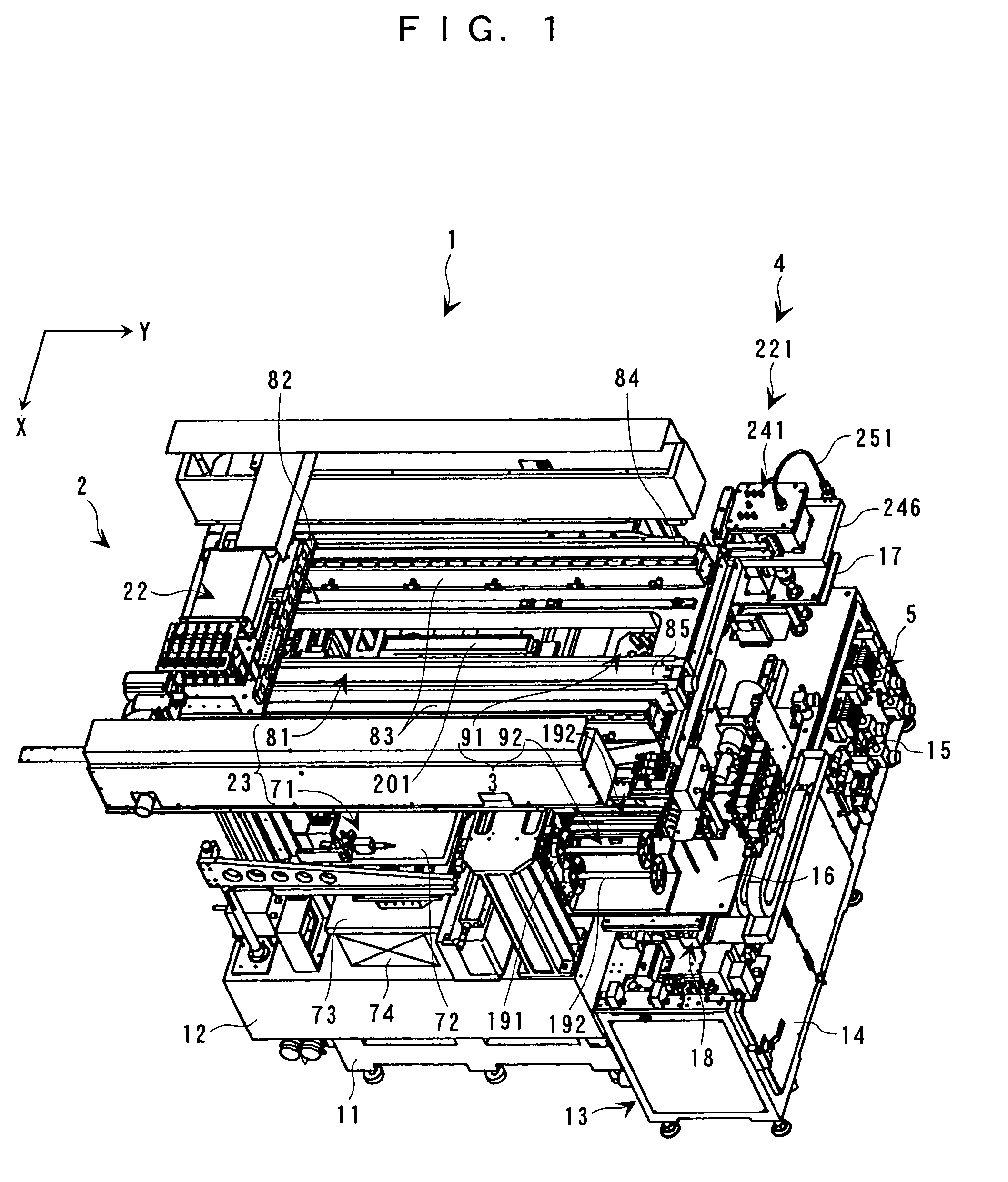
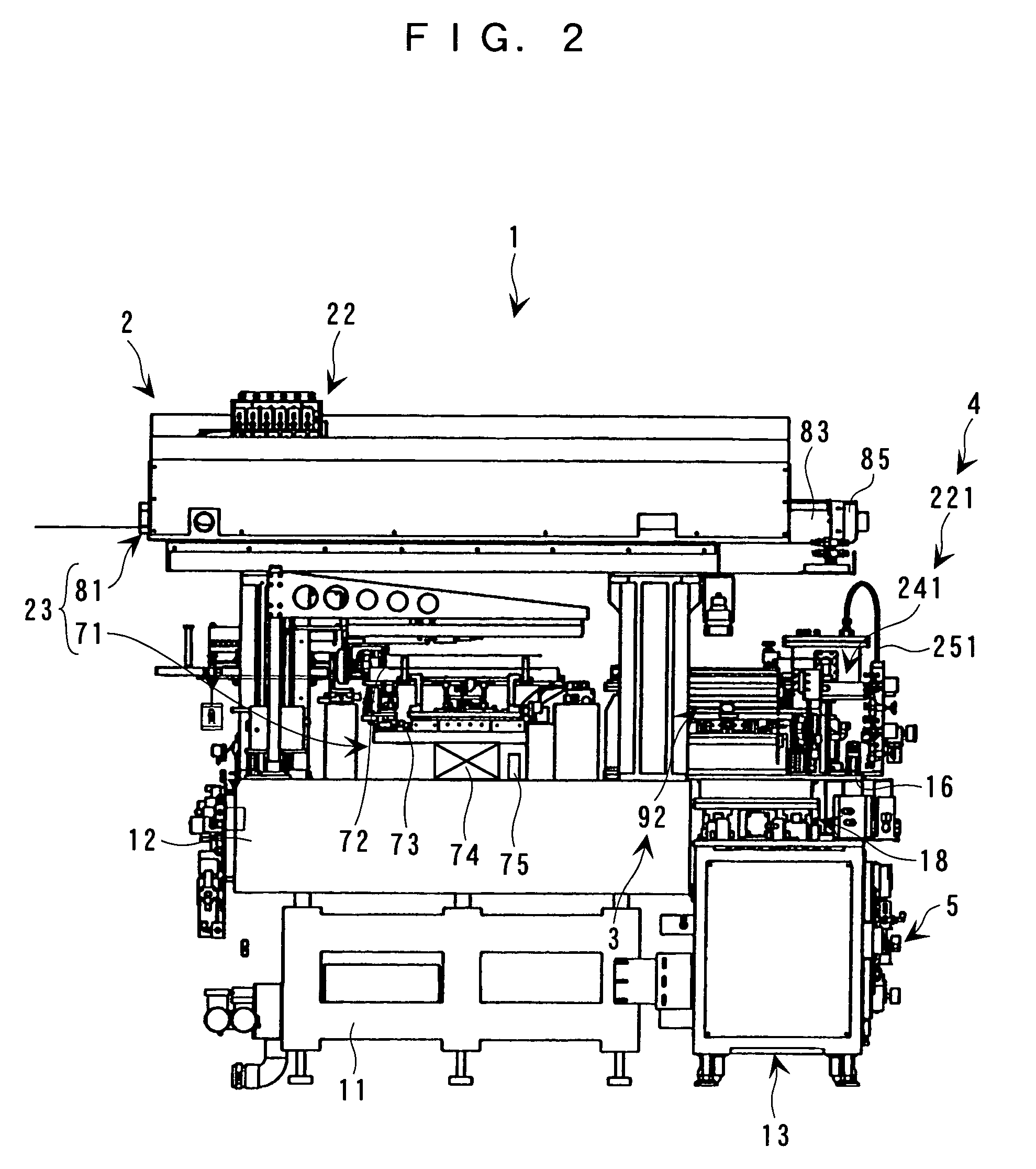
[0061]With reference to the accompanying drawings, an embodiment of this invention will be described below. FIG. 1 is an external perspective view of an imaging apparatus to which this invention is applied. FIGS. 2 to 4 are front view, right side view and partial plan view of the imaging apparatus to which this invention is applied. As described later in detail, this imaging apparatus 1 is configured to form a film formation part of a liquid droplet on a workpiece W such as a substrate by introducing a function liquid such as a particular ink and a luminescent resin liquid into a liquid droplet ejection head 31.

[0062]As shown in FIGS. 1 to 4, the imaging apparatus 1 includes: imaging means 2 for ejecting the function liquid while moving the liquid droplet ejection head 31 relatively to the workpiece W; maintenance means 3 for performing maintenance of the liquid droplet ejection head 31; function liquid supply / recovery means 4 for supplying the liquid droplet ejection head 31 with t...


PUM


Abstract

In an imaging apparatus having a head unit mounting thereon liquid droplet ejection heads with a plurality of ejection nozzles, a confirmation is made before starting an imaging operation as to whether or not liquid droplets are normally ejected from the respective ejection nozzles. This confirmation is made by using optical liquid droplet detectors having a light emitting element and a light receiving element. When ejection of liquid droplets from any of the ejection nozzles of liquid droplet ejection heads is determined to be abnormal in an ejection confirming operation, the ejection confirming operation is performed again. When the ejection of the liquid droplets from the same ejection nozzle is determined to be abnormal also in this ejection confirming operation, this ejection nozzle is judged to be abnormal.

Description

BACKGROUND OF THE INVENTION[0001]1. Field of the Invention[0002]This invention relates to a method of determining abnormality of nozzles in an imaging (drawing) device using a liquid droplet ejection (or discharge) head having a plurality of ejection (or discharge) nozzles as represented by an ink jet head; an imaging apparatus; an electrooptic device; a method of manufacturing the electrooptic device; and an electronic equipment.[0003]2. Description of the Related Art[0004]An ink jet head (a liquid droplet ejection head) of an ink jet printer can accurately eject dot-shaped minute ink droplets (liquid droplets). Thus, by using a function liquid (hereinafter referred to as function liquid) such as a particular ink or photosensitive resin, for example, as an ejected liquid, the ink jet head is expected to be applied to a field of manufacturing of various devices.[0005]For example, it is considered to manufacture a color filter of a liquid crystal display, an organic electroluminescen...

Claims


Application Information

Patent Timeline
IPC IPC(8): B41J29/393B41J2/01B05D3/00B05D7/00B41J2/05B41J2/135B41J2/165B41J29/02G02B5/20G02F1/1335G02F1/1339H01J9/02H01J11/22H01J11/34H01L51/50H05B33/10
CPCB41J2/0451B41J2/0456B41J2/04586B41J29/02B41J29/393B41J2/16579B41J2202/09B41J2/135
Inventor NAKAMURA, SHINICHI
Owner KATEEVA
Why Eureka
Try Eureka