
Connection apparatus for circuit board, ink jet type recording apparatus using the same, IC chip and ink cartridge having IC chip

a technology of ink jet type recording apparatus and connection apparatus, which is applied in the direction of printed circuit, printed circuit aspects, printed circuit manufacture, etc., can solve the problems of circuit board b>27/b> damage, and the inability to normal print operation of recording apparatus, so as to prevent the occurrence of long-term electrical poor contact

Inactive Publication Date: 2006-09-05
SEIKO EPSON CORP
View PDF13 Cites 25 Cited by
  • Summary
  • Abstract
  • Description
  • Claims
  • Application Information

AI Technical Summary

Benefits of technology

[0014]This invention is accomplished by focusing attention to the aforementioned problems. Accordingly, an object of the invention is to provide a connection apparatus for a circuit board, which is enabled to prevent an occurrence of long-term electrical poor contacting. Moreover, another object of the invention is to provide an ink jet type recording apparatus enabled to ensure proper printing operation over a long time period. Yet another object of the invention is to provide an IC chip having a structure that can eliminate the aforementioned problems. Still another object of the invention is to provide an ink cartridge having an IC chip that can eliminate the aforementioned problems.
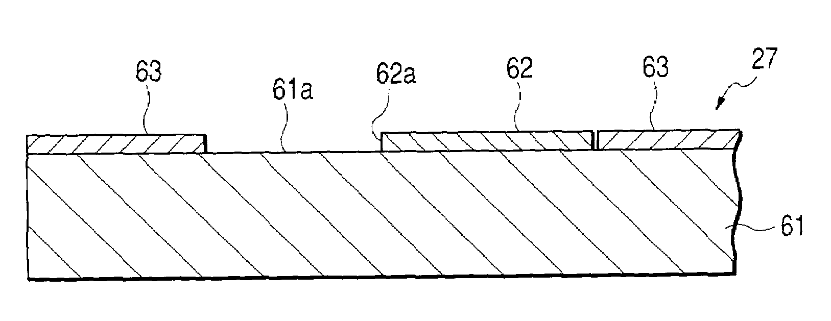
[0018]Therefore, the frequency of causing dust to intervene between the contact pad and the connector terminal can be reduced. The reliability of the electrical contact between the connector terminal and the contact pad can be ensured. Further, the effect of wiping the dust adhering to the connector terminal can be enhanced because the step portion is constituted by metal foil that constitutes the contact pad.
[0020]In the case of employing such a configuration, the end portion of the connector terminal overrides the projecting part and then comes in slide contact with the circuit board surface. Subsequently, the end portion runs upon the top surface of the dummy pattern formed from metallic foil. Then, the end portion comes in slide contact with the top surface of the resist film. Finally, the end portion comes in contact with the top surface of the contact pad. When the connector terminal runs upon the top surface of the dummy pattern, the dust adhering to the connector terminal is wiped by the step portion formed owing to the thickness of the dummy pattern at the front end part of the dummy pattern by the action of such a sliding-contact operation. Therefore, the frequency of causing dust to intervene between the contact pad and the connector terminal can be reduced. The reliability of the electrical contact between the-connector terminal and the contact pad can be ensured.
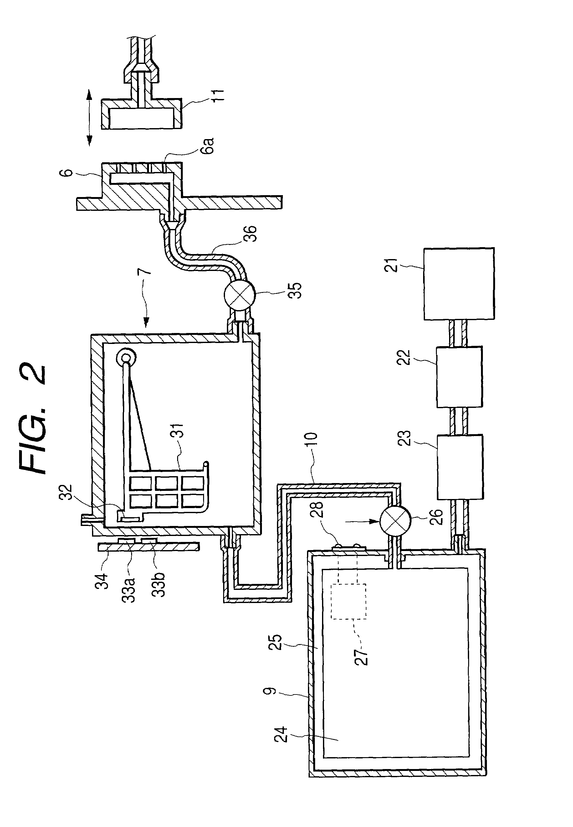
[0023]According to the ink jet type recording apparatus of the aforementioned configuration, the operations and effects of the aforementioned connection apparatus for a circuit board can be obtained. Moreover, information on the cartridge can be accurately transferred between the cartridge and the main unit of the recording apparatus. Therefore, proper printing operation of the recording apparatus can be assured The reliability of an operation of such a kind of an ink jet type recording apparatus can be ensured.

Problems solved by technology

This material has a problem that when the connector terminals 70 directly touches the end portion, the glass material chips and thus, the circuit board 27 is damaged.
Thus, in the case of utilizing the apparatus of this configuration in managing the ink cartridges in the ink jet type recording apparatus, obstacles, such as disablement of normal printing operation of the recording apparatus, occur.

Method used


Image

  • Connection apparatus for circuit board, ink jet type recording apparatus using the same, IC chip and ink cartridge having IC chip
  • Connection apparatus for circuit board, ink jet type recording apparatus using the same, IC chip and ink cartridge having IC chip
  • Connection apparatus for circuit board, ink jet type recording apparatus using the same, IC chip and ink cartridge having IC chip

Examples


Embodiment Construction

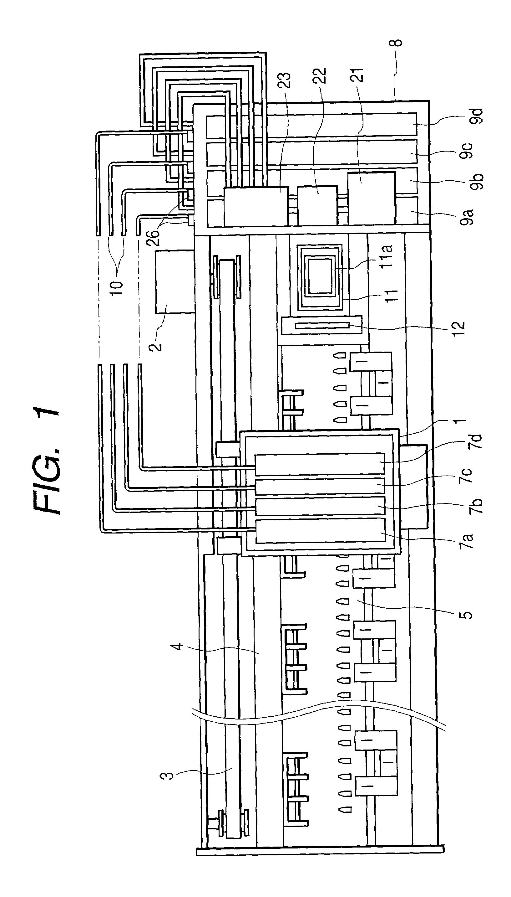
[0137]Hereinafter, an embodiment of this invention, which is a connection apparatus for a circuit board according to this invention applied to an ink jet type recording apparatus, is described. Referring first to FIG. 1, there is shown a top view of the entire configuration of the inkjet type recording apparatus that can preferably utilize this invention. In FIG. 1, reference character 1 designates a carriage. This carriage 1 is configured so as to reciprocatively be moved in a longitudinal direction of a paper feed member 5 guided by a scanning guide member 4, that is, a main scanning direction, which is a direction of width of recording paper, through a timing belt 3 driven by a carriage motor 2. Further, although not shown in FIG. 1, an ink jet type recording head 6 (to be described later) is mounted on the carriage 1.

[0138]Furthermore, subtanks 7a to 7d for supplying ink to the recording head are mounted on the carriage 1. In this embodiment, these subtanks 7a to 7d are four tan...


PUM


Abstract

A circuit board on an ink cartridge has contact pads which are electrically conducted to a semiconductor storage element mounted on the circuit board. Connector terminals on an ink jet recording apparatus are brought into relative slide contact with a surface of this circuit board, and electrically connected to the contact pads. When the connector terminals come in contact with the contact pads, the dust adhering to the connector terminals is wiped and removed by step portions that are constituted by no-resist-film formation parts and that are adjacent to the contact pads. Consequently, the reliability of the electrical contact between the connector terminals and the contact pads is ensured.

Description

BACKGROUND OF THE INVENTION[0001]This invention relates to a connection apparatus for a circuit board configured so that connector terminals come in relative slide contact with contact pads formed on a circuit board surface from a direction of a surface of the circuit board and electrically conducted thereto, and also relates to an ink jet type recording apparatus using this connection apparatus for a circuit board. The present invention further relates to an IC chip (a circuit board) having contact pads and a memory device on a base (a substrate), and to an ink cartridge having the IC chip.[0002]For example, an inkjet type recording apparatus is configured so that a plurality of ink cartridges to be used therefor are detachably supported by a cartridge holder and that ink of each color is supplied to a recording head. Recently, there have been provided products of such a kind of a recording apparatus, which are configured so that information on the kind, color, and remaining amount...

Claims


Application Information

Patent Timeline
IPC IPC(8): B41J2/14B41J2/175H05K1/11H05K3/34
CPCB41J2/17509B41J2/17513B41J2/1752B41J2/17523B41J2/1753B41J2/17566H05K1/117H05K3/3452B41J2/17546H05K2201/0989H05K1/11H05K2201/09709B41J2/175
Inventor ARUGA, YOSHIHARU
Owner SEIKO EPSON CORP
Learn More