
Rotary bed sorption system including at least one recycled isolation loop, and methods of designing and operating such a system

a technology of sorption system and rotary bed, which is applied in the direction of heating type, lighting and heating apparatus, separation process, etc., can solve the problems of no prior art teaching of the use of one or more zones, and the concentration of vapor being removed is affected, so as to reduce cross-contamination

Active Publication Date: 2006-09-05
MANTERS CORP
View PDF35 Cites 35 Cited by
  • Summary
  • Abstract
  • Description
  • Claims
  • Application Information

AI Technical Summary

Benefits of technology

[0008]The present invention uses one or more isolation loops to reduce cross-contamination between sorption and desorption zones of rotary sorption beds caused by pressure imbalances and large vapor pressure differences of the various fluid streams.
[0019]In yet another embodiment of the invention, a method of improving the performance of a rotary bed sorption system includes steps of rotating a mass of a regenerable sorbent material so that, in a cycle of operation, a given volume of the sorbent mass sequentially passes through first, second, third, and fourth zones, before returning to the first zone; passing the process fluid stream through the first zone in a first direction; passing the regeneration fluid stream through the third zone in a second direction that is opposite the first direction; and reducing cross-contamination between the process fluid stream and the regeneration fluid stream by recycling at least one isolation fluid stream between the sorbent mass in the second zone, where the isolation fluid stream passes through the sorbent mass in the second direction, and in the fourth zone, where the isolation fluid stream passes through the sorbent mass in the first direction.

Problems solved by technology

Contamination can result from pressure differences in the fluid streams themselves, or vapor pressure differences within the matrix of the rotating sorbent disk.
Another source of possible contamination lies in areas of the sorbent disk that are adjacent to the active sorptive area, but that do not see active fluid flow during the cycle.
The vapor pressure difference overcomes the diffusive force of the structure, and trace amounts of vapor are released into the treated fluid stream, causing detrimental increases in the concentration of the vapor being removed.
However, there are believed to be no teachings in the prior art of the use of one or more zones to reduce the diffusion of moisture through the sorbent matrix from a higher-concentration fluid stream, or to reduce the carryover of vapor from a higher-pressure fluid stream to a lower-pressure fluid stream.

Method used


Image

  • Rotary bed sorption system including at least one recycled isolation loop, and methods of designing and operating such a system
  • Rotary bed sorption system including at least one recycled isolation loop, and methods of designing and operating such a system
  • Rotary bed sorption system including at least one recycled isolation loop, and methods of designing and operating such a system

Examples


Embodiment Construction

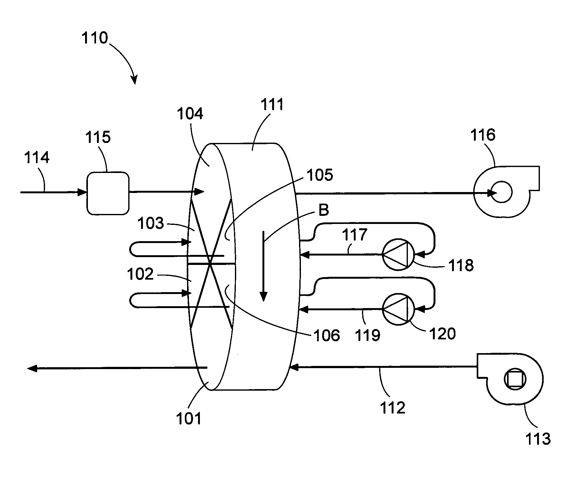
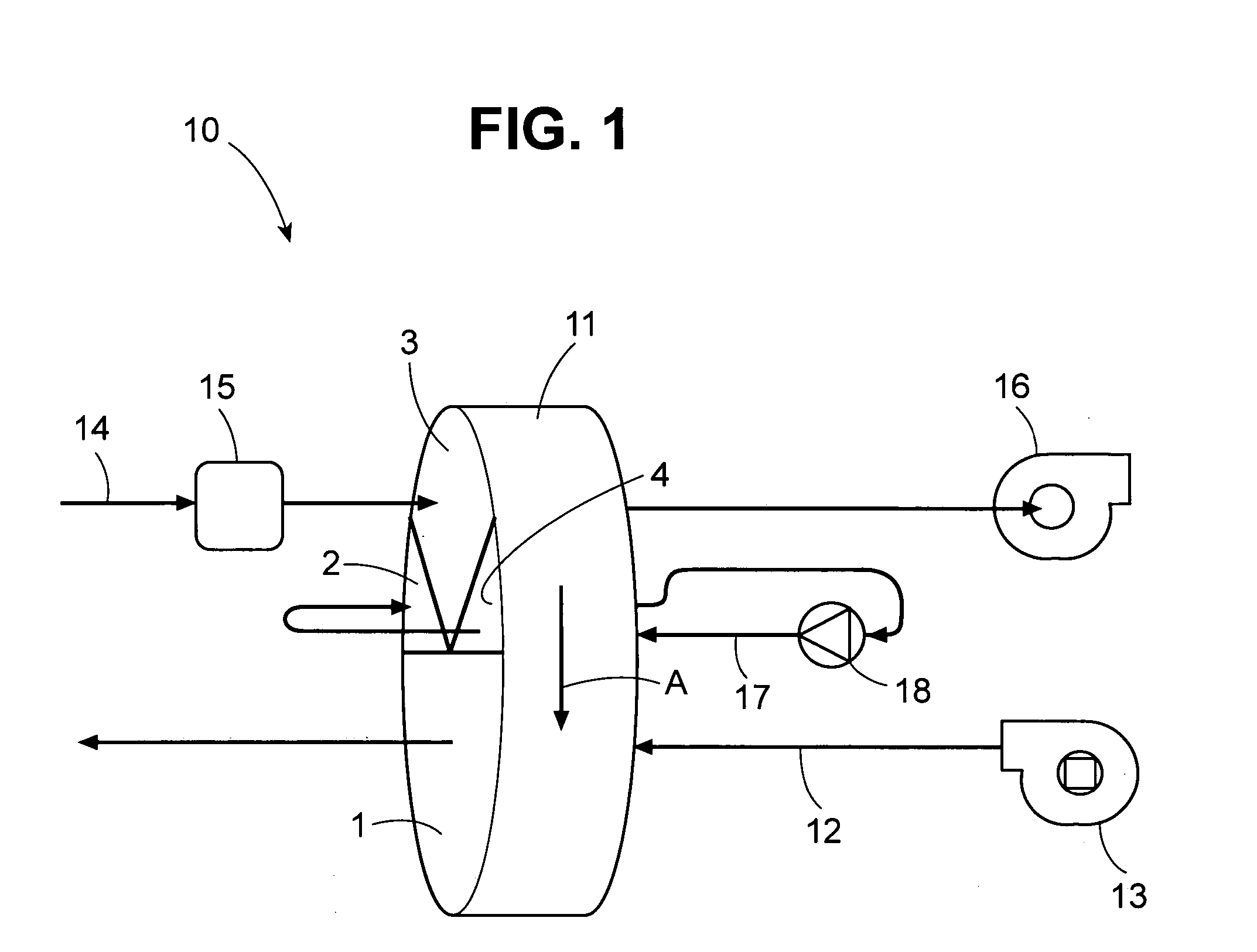
[0039]FIG. 1 illustrates a first preferred embodiment of a rotary sorption bed system 10 in accordance with the present invention. The system includes a rotating disk-shaped porous mass 11 of a conventional construction containing or coated with regenerable sorbent material that, in a cycle of operation, sequentially passes through a first zone 1, a second zone 2, and third zone 3, and a fourth zone 4. The sorbent mass 11 is rotated about its axis in the direction indicated by arrow A by a known rotor mechanism (not shown).

[0040]A process fluid stream 12 carrying a sorbate (e.g., water vapor) is passed through the sorbent mass 11 in the first zone 1, where the sorbate is sorbed (i.e., loaded) onto the sorbent mass 11. The process fluid stream exiting the sorbent mass has a reduced sorbate concentration compared to the process fluid stream entering the sorbent mass. Optionally, a fan, blower, or other fluid-moving device 13 can be used to drive the process fluid flow through duct wor...


PUM

PropertyMeasurementUnit
dew pointaaaaaaaaaa
vapor pressureaaaaaaaaaa
dew pointsaaaaaaaaaa

Abstract

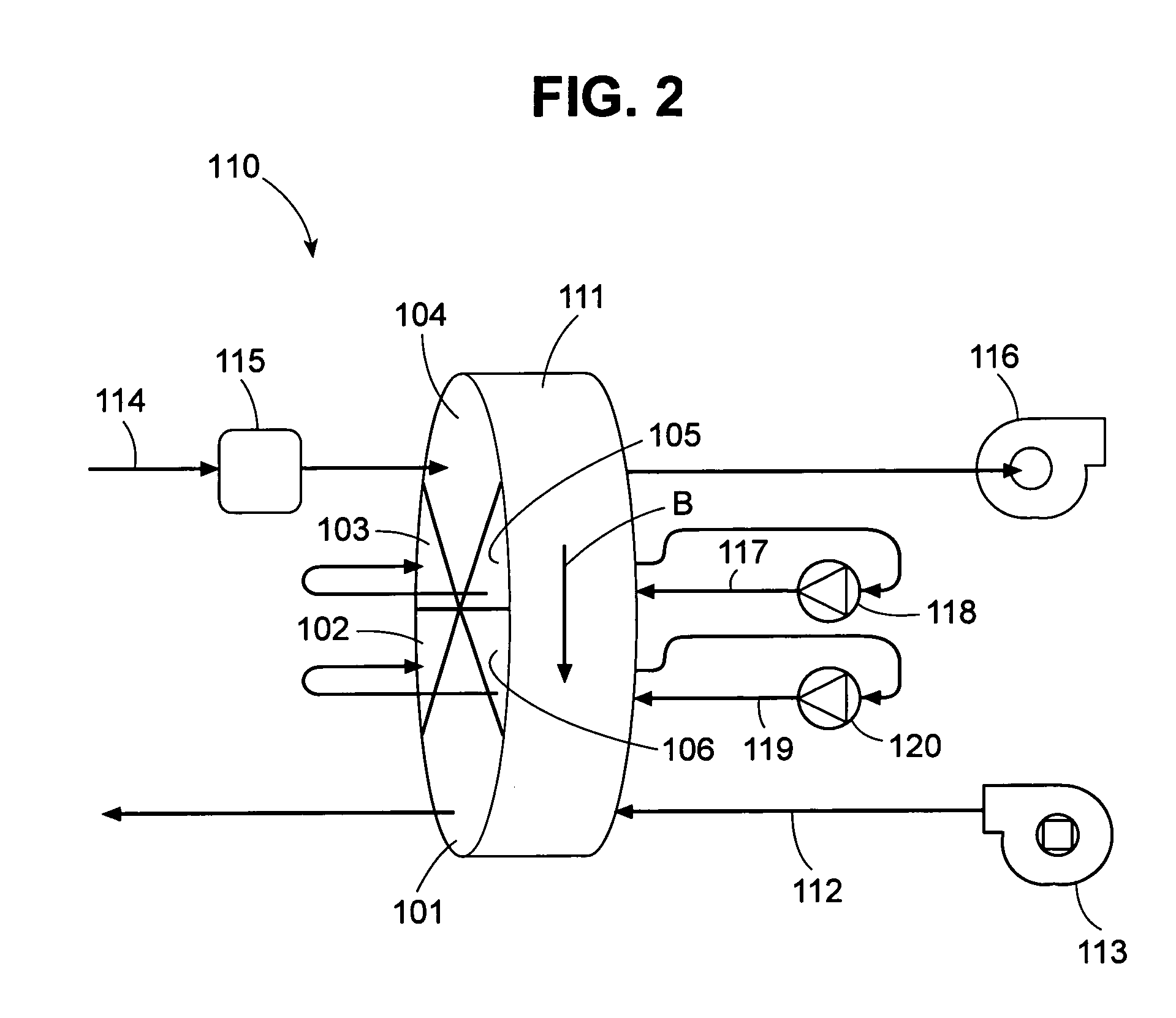
A method of reducing the sorbate concentration of a process fluid stream using a sorption bed system includes the following steps. A mass of a sorbent material is rotated so that, in a cycle of operation, a given volume of the sorbent mass sequentially passes through first, second, third, fourth, fifth, and sixth zones, before returning to the first zone. A process fluid stream is passed through the sorbent mass in the first zone, and a regeneration fluid stream is passed through the sorbent mass in the fourth zone. A first isolation fluid stream is recycled in a closed loop, independent of the process fluid stream and the regeneration fluid stream, between the sorbent mass in the second zone and in the sixth zone. A second isolation fluid stream, meanwhile, is recycled in a closed loop, independent of the process fluid stream, the regeneration fluid stream, and the first isolation fluid stream, between the sorbent mass in the third zone and in the fifth zone.

Description

BACKGROUND OF THE INVENTION[0001]1. Field of the Invention[0002]The present invention relates generally to a rotary bed sorption system, and, in particular, to a rotary bed sorption system that includes one or more recycled isolation loops. The invention also relates to methods of designing and operating such a system.[0003]2. Description of the Related Art[0004]Rotary bed sorption systems have long been used to collect a sorbate from one fluid stream, sometimes called a process or sorption fluid stream, and transfer it, in a more concentrated form, to a second fluid stream, sometimes called a desorption or regeneration fluid stream. Commonly-removed sorbates include water vapor, volatile organic compounds (“VOCs”), nitrous oxides (“NOx”), and the like.[0005]It is important in a rotary bed sorption system, particularly one in which a low sorbate concentration is desired in the treated fluid, to minimize any cross-contamination between the process fluid stream and the regeneration fl...

Claims


Application Information

Patent Timeline
Patent Type & Authority Patents(United States)
IPC IPC(8): B01D53/06F24F3/14
CPCB01D53/06F24F3/1423B01D53/261B01D2253/106B01D2257/402B01D2257/708B01D2257/80Y02C20/10B01D2259/4009F24F2203/1032F24F2203/1056F24F2203/1068F24F2203/1092B01D2259/40081
Inventor DINNAGE, PAUL A.BRICKLEY, STEPHEN C.
Owner MANTERS CORP
Learn More