Vehicle actuated road imbedded magneto generator

a technology of imbedded magneto generators and vehicles, which is applied in the direction of electric generator control, machines/engines, transportation and packaging, etc., can solve the problems of not being able to describe an electrical generating system and the efficiency of devices

Inactive Publication Date: 2006-09-05
HUNTER JR JOHN P
View PDF32 Cites 98 Cited by
  • Summary
  • Abstract
  • Description
  • Claims
  • Application Information

AI Technical Summary

Benefits of technology

[0011]It is also an object of the present invention to provide a low cost energy generation system.
[0021]To produce electrical energy, the elongated hollows have mounted therewithin a plurality of vertically spaced-apart electrical coils, each having a respective central aperture, which central apertures are each a central vertically extending void through which the plunger extends. The plunger has a plurality of vertically spaced-apart magnets mounted thereon, which magnets are vertically movable with the movement of the plunger alternately between the raised and the lowered positions. The magnet movement is in close electrically-generating effective proximity to the coil, so that the magnet movement causes a flow of electrons within the coils. These coils are electrically connected so as to effectively and usefully collect the energy arising from the induced electron flow within the coils.
[0026]One or more of the spaced-apart elongated hollows are positioned in close proximity to each other in an electrical generating module, which module has a hinged top plate acting as a cam, wherein the cam is in mechanical contact with the plungers of at least two of the spaced-apart elongated hollows. The cam is rotatably movable between a raised position and a depressed position when actuated by downwardly directed vehicle tire pressure. The cam downwardly depresses simultaneously each plunger within the plurality of spaced-apart elongated hollows for synchronizing the electrical output of the plurality of spaced-apart elongated hollows.
[0028]A bridge rectifier may be provided for preventing reverse current flow during electrical generation, wherein the vertically spaced-apart electrical coils are wired in series and the electrical generating module has at least one bridge rectifier to produce high-voltage uni-directional voltage pulses with each stroke of the plungers within the plurality of spaced-apart elongated hollows.

Problems solved by technology

These devices are not efficient because of the extra auxiliary mechanical step in producing electrical energy.
However, these patents do not describe an electrical generating system wherein a plurality of linear operating magnetos are physically imbedded within a roadway pavement.

Method used


Image

  • Vehicle actuated road imbedded magneto generator
  • Vehicle actuated road imbedded magneto generator
  • Vehicle actuated road imbedded magneto generator

Examples


Embodiment Construction

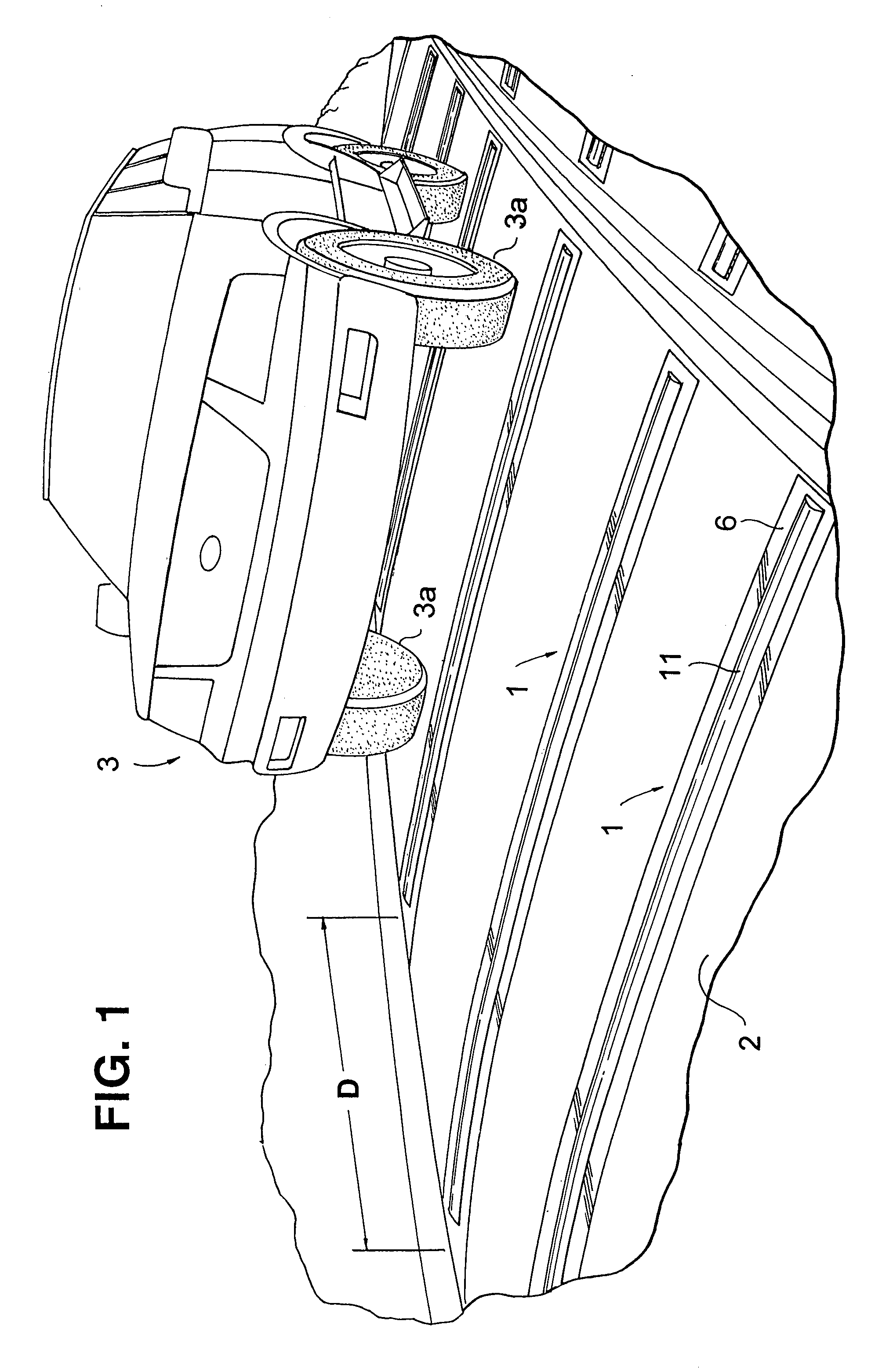
[0040]FIG. 1 shows multiple generating modules 1 installed in the expansion joints between blocks of concrete road surface 2. They fit across an entire traffic lane width and therefore engage tires on both sides of a vehicle. Distance D from one generating module 1 to the next is approximately 60 feet (18 meters). expansion joints within the roadway.

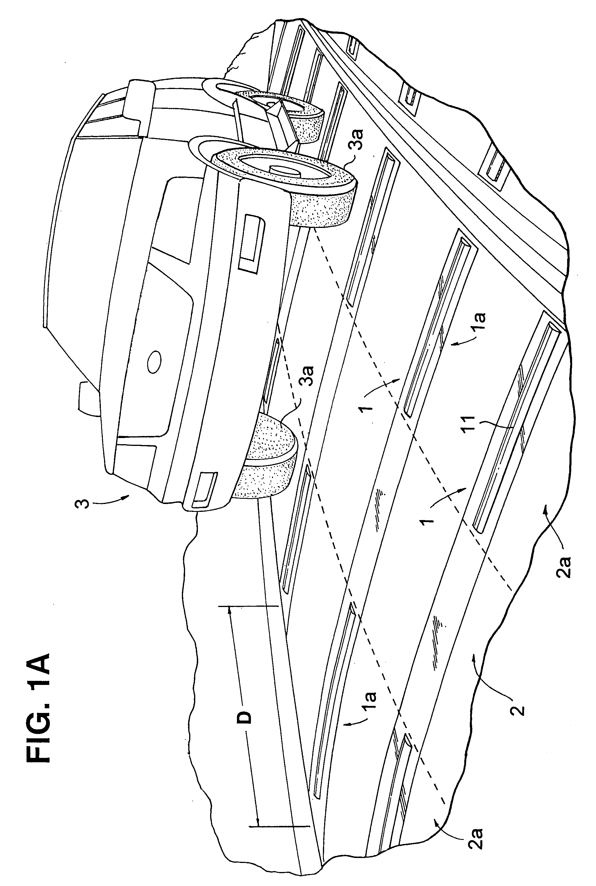
[0041]As further shown in FIG. 1, while modules 1 may extend across an entire length of road surface 2, preferably in an alternate embodiment shown in FIG. 1A, these spaced-apart modules 1 can be arranged in one or more longitudinal bands 1a, (indicated by the darkened cross-hatched portions of modules 1) which encompass elongated area portions 2a of roadway surface 2 parallel to the direction of vehicular travel, so that at least one longitudinal band 1a is positioned in an elongated area portion 2a of the surface 2 of the roadway having the greatest likelihood of being contacted by the tires 3a of vehicles 3 on the roadway i.e., in the...


PUM


Abstract

An electrical generating system includes a plurality of linear operating magnetos impeded within a roadway pavement, whereby the passage of vehicle wheels from moving motor vehicles directly depresses linear solenoid plungers for generating electricity, without the need for the extra energy consumption drawbacks, such as bellows, compressed air or ratchet mechanisms.

Description

FIELD OF THE INVENTION[0001]The present invention relates to vehicle actuated road imbedded magneto generators.BACKGROUND OF THE INVENTION[0002]Among related patents include U.S. Pat. No. 6,204,568 of Runner, which has a ratchet plunger connected to air flow turbines for converting mechanical motion of vehicles moving in traffic to electrical energy.[0003]Also, U.S. Pat. No. 4,614,875 of McGee has a similar vehicle wheel actuated electrical generator such as a rotor and stator generator, i.e., an AC generator or a DC dynamo.[0004]The other patents disclose auxiliary mechanical devices such as inflatable bladders or gears that produce mechanical energy which is converted to electrical energy by a generator. These devices are not efficient because of the extra auxiliary mechanical step in producing electrical energy.[0005]For example, U.S. Pat. No. 4,339,920 of Le Van, U.S. Pat. No. 4,322,673 of Dukess, U.S. Pat. No. 4,418,542 of Ferrell, U.S. Pat. No. 4,081,224 of Krupp, U.S. Pat. No...

Claims


Application Information

Patent Timeline
Patent Type & Authority Patents(United States)
IPC IPC(8): F03G3/00B60L11/18H02K35/02H02P9/04
CPCB60L11/182H02K35/02Y02T90/14Y02T10/7005Y02T90/122Y02T10/641Y02T10/7072Y02T10/64Y02T10/70Y02T90/12
Inventor HUNTER, JR., JOHN P.
Owner HUNTER JR JOHN P
Why Eureka
Try Eureka