Method for preventing collisions involving motor vehicles

a technology for motor vehicles and collisions, applied in the direction of tractors, instruments, using reradiation, etc., can solve the problems of braking intervention, inability to reliably prevent collisions, and affecting the comfort and safety of the occupants of the vehicle,

Inactive Publication Date: 2006-09-05
ROBERT BOSCH GMBH
View PDF21 Cites 42 Cited by
  • Summary
  • Abstract
  • Description
  • Claims
  • Application Information

AI Technical Summary

Benefits of technology

[0007]The object of the present invention is achieved by providing that at least one of the responses to a detected collision risk is a preparatory measure accelerating the implementation of a command, which may be output later, to decelerate the vehicle, without the preparatory measure itself having any significant decelerating effect on the vehicle.
[0009]A significant portion of the response time which elapses between triggering of a braking command and the actual point in time when the vehicle brake becomes effective is attributable to unavoidable dead volumes in the hydraulic system of the brake system. These dead volumes must first be filled with brake fluid before the brake shoes come into frictional contact with the brake disks or brake drums of the wheel brakes and the brake becomes effective. The time required for filling the dead volumes is approximately 200 ms to 300 ms in the conventional brake systems. At a driving speed of approximately 30 m / s (108 km / h) this corresponds to lengthening the stopping distance by up to 9 meters.
[0011]In an example embodiment of the present invention, such a command for priming the brake system is generated as a function of the calculated collision probability. In this way, the vehicle is put in a condition of increased braking readiness when there is a medium collision risk, so that when the collision risk is confirmed and a braking intervention measure is necessary, the braking effect begins much more rapidly.
[0012]“Priming” of the brake system is understood here to refer in general to a measure which puts the brake system in a state in which it is able to respond more quickly to a braking command, without the measure itself resulting in a significant braking effect. This priming of brakes may be accomplished, for example, by building up a certain brake pressure in the wheel brake cylinders and / or in the components of the hydraulic system immediately upstream from them, so that the brake shoes are already approaching the brake disk or brake drum of the wheel brake or are even in contact with it without exerting any mentionable frictional force. As an alternative or in addition, the priming of brakes may also be accomplished by providing a certain prepressure in a pressure accumulator or in a brake booster, which permits more rapid filling of the dead volume when the brakes are actually operated.
[0013]In vehicles having an ACC system providing measures for intervening in the brake system, it is generally necessary to switch between engine operation, in which positive or negative acceleration of the vehicle is achieved through driving torque alone, i.e., the engine drag, and braking operation, in which vehicle deceleration is achieved by operation of the brakes. To prevent “fluttering” in switching between engine operation and braking operation, the present invention provides for the switching to be performed as a function of an acceleration request signal with a certain hysteresis. Switching from engine operation to braking operation is performed when the acceleration request signal falls below a low threshold value, and returns to engine operation when the acceleration request signal exceeds a higher threshold value which corresponds to the vehicle deceleration achievable by engine drag. However, although this hysteresis characteristic is desirable per se, it results in the braking intervention taking place only with a certain time lag, namely only when the acceleration request signal has reached the lower threshold value. Therefore, a “preparatory measure” in accordance with the present invention may therefore also include reduction of the hysteresis interval when there is a moderate collision risk and possibly set it back completely at zero, so that the braking command is generated immediately when the engine drag is no longer sufficient to achieve the required vehicle deceleration.
[0014]In automobiles having an automatic transmission, one preparatory measure would also involve automatically downshifting to a lower gear when there is a moderate collision risk—without an immediate change in setpoint acceleration—so that a greater engine drag is available for vehicle deceleration even in engine operation. This measure also has the advantage that in many cases it is possible to respond to a temporary disturbance in traffic flow without a braking intervention, so that the following traffic is not irritated by flickering of the brake lights, and after the disturbance has passed, it is possible to accelerate back up to the desired speed more rapidly.

Problems solved by technology

However, when greater deceleration of the vehicle is required, e.g., on a downward slope or due to the distance from the vehicle in front, and the engine drag is not enough to achieve adequate deceleration of the vehicle, then the system intervenes in the brake system of the vehicle.
In these methods, however, there are problems in determining the criteria for triggering of stage 2 because of the unavoidable uncertainty in estimating the collision risk.
If the threshold for triggering of this stage is set too high, collisions cannot be reliably prevented.
However, if this threshold is lowered, it results in unnecessary braking maneuvers, because of an incorrect appraisal of the collision risk; the unnecessary braking may also have a negative effect on the comfort and feeling of safety of the occupants of the vehicle, while irritating the following traffic or even becoming the cause of rear-end collisions in the following traffic.
A significant portion of the response time which elapses between triggering of a braking command and the actual point in time when the vehicle brake becomes effective is attributable to unavoidable dead volumes in the hydraulic system of the brake system.
However, although this hysteresis characteristic is desirable per se, it results in the braking intervention taking place only with a certain time lag, namely only when the acceleration request signal has reached the lower threshold value.

Method used


Image

  • Method for preventing collisions involving motor vehicles
  • Method for preventing collisions involving motor vehicles
  • Method for preventing collisions involving motor vehicles

Examples


Embodiment Construction

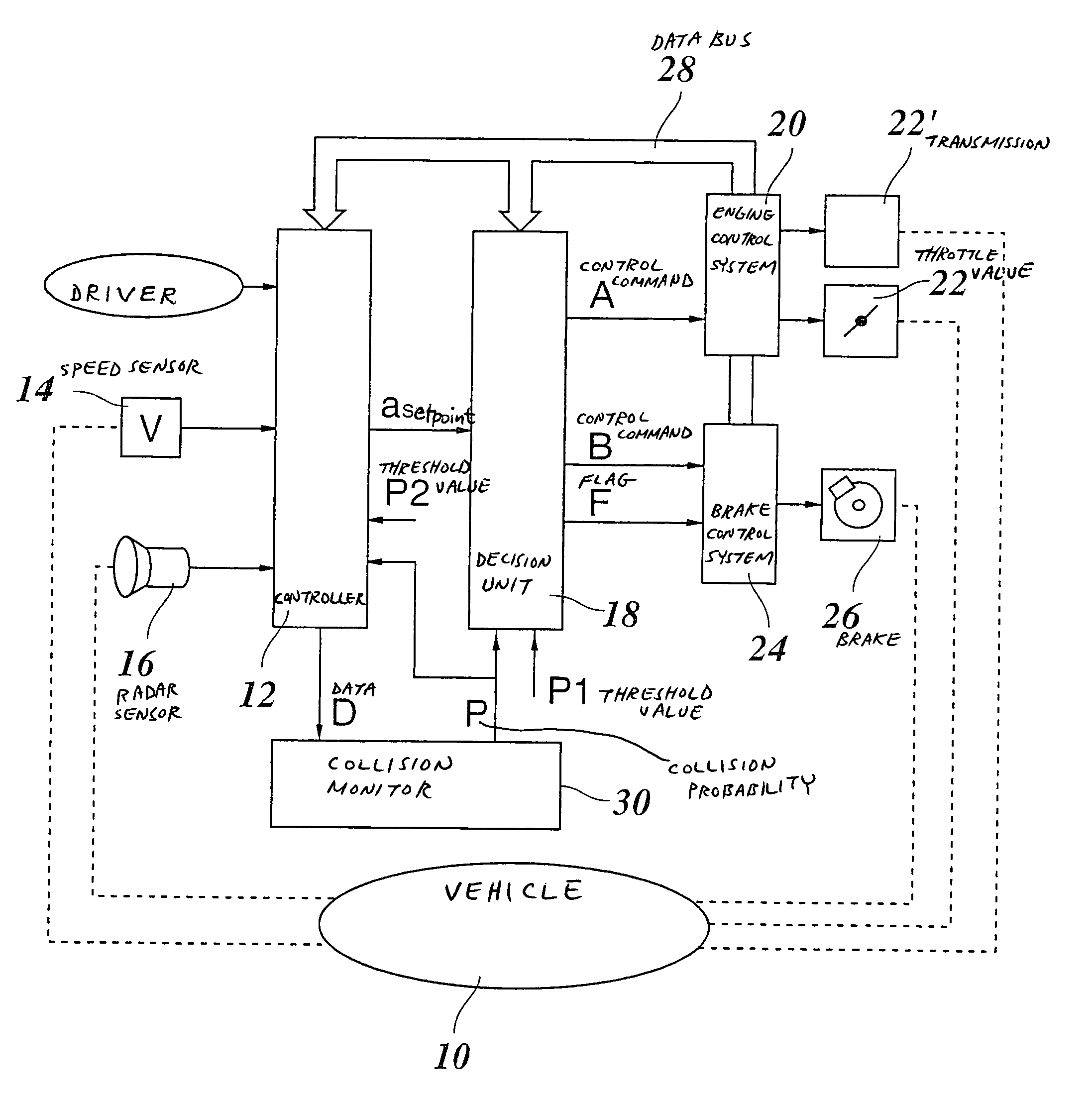
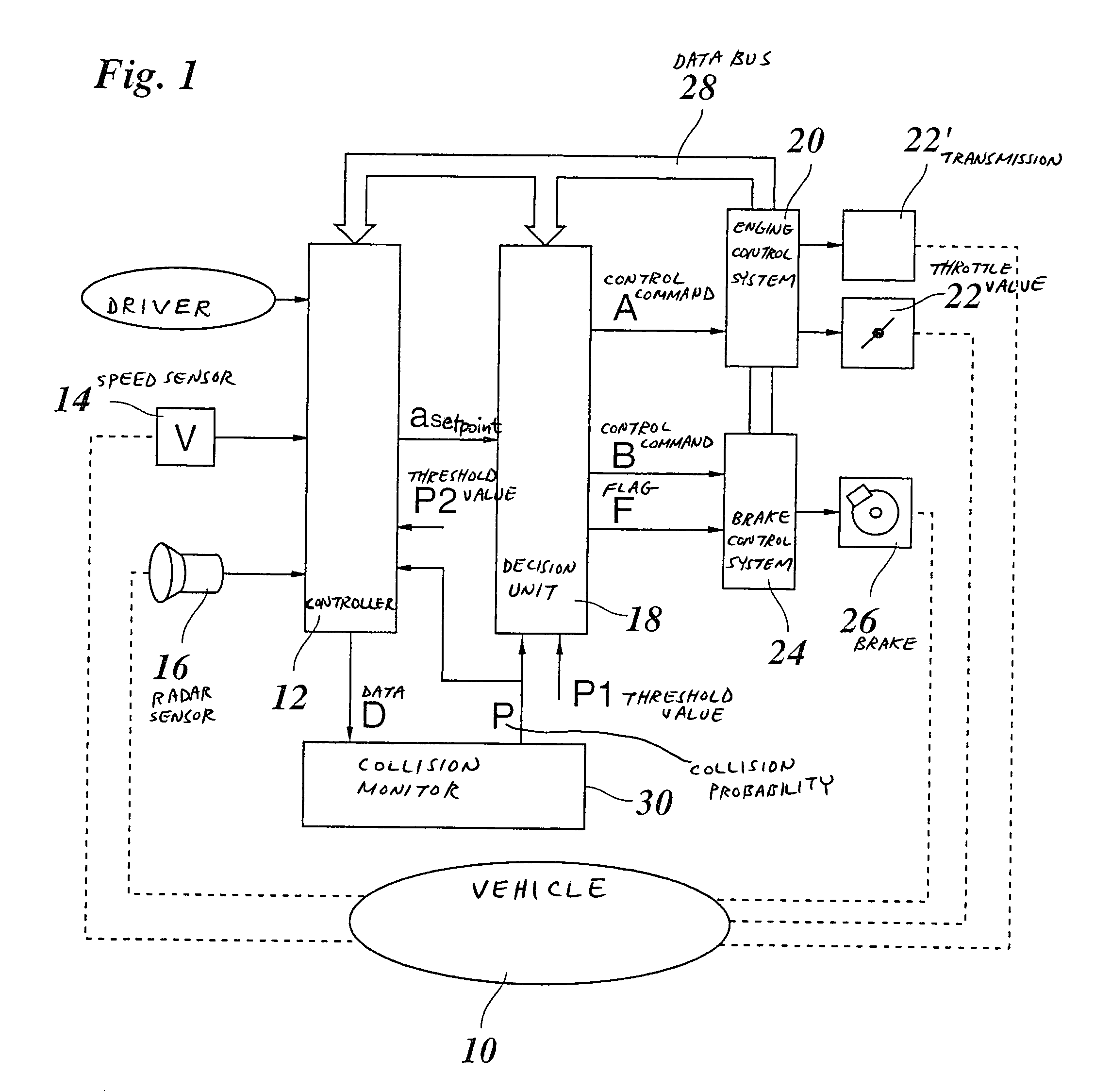
[0019]FIG. 1 symbolically shows a motor vehicle 10, the speed of which is regulated with the help of an ACC system. A controller 12 receives a signal from a speed sensor 14 indicating the actual speed of the vehicle. In addition, a positioning device is mounted on the front of the vehicle; in the present example, this is a radar sensor 16 which reports distance and relative velocity data on objects located in front of the vehicle to controller 12. Radar sensor 16 preferably has a certain angular resolution, so the azimuth angle of the objects located may also be detected and reported to controller 12. It is possible in this way for the radar sensor 16 and / or controller 12 to differentiate vehicles traveling ahead in one's own lane from vehicles in other lanes and stationary targets at the edge of the road surface. If vehicles driving in front are in one's own lane, the vehicle immediately in front is selected as a target object and the speed of vehicle 10 is regulated so as to maint...


PUM


Abstract

A collision prevention method for motor vehicles is provided, in which method obstacles in front of the vehicle are detected by an on-board positioning system, a collision probability is calculated from the position data, and one or more responses to prevent a collision are triggered as a function of the collision probability. At least one of the responses is a preparatory measure accelerating the implementation of a command, which may be output later, to decelerate the vehicle, without the preparatory measure itself having any significant decelerating effect on the vehicle.

Description

FIELD OF THE INVENTION[0001]The present invention relates to a collision prevention method for motor vehicles, in which method obstacles in front of the vehicle are detected by an on-board positioning system, a collision probability is calculated from the position data, and one or more responses to prevent a collision are triggered as a function of the collision probability.BACKGROUND INFORMATION[0002]A collision-prevention method, in particular for use in combination with a system for adaptive cruise control in motor vehicles, is described in the publication “Adaptive Cruise Control System—Aspects and Development Trends” by Winner, Witte, Uhler and Lichtenberg, Robert Bosch GmbH, in SAE Technical Paper Series 961010, International Congress & Exposition, Detroit, Feb. 26–29, 1996. The Adaptive Cruise Control (ACC) system described in this publication is based on a distance sensor, for example, a multi-target-capable radar sensor mounted on the front of the vehicle to measure distanc...

Claims


Application Information

Patent Timeline
Patent Type & Authority Patents(United States)
IPC IPC(8): B60Q1/00B60K31/00B60T7/12B60T7/22B60T8/1761B60W30/16F16H61/02F16H61/68
CPCB60K31/0008B60W30/16B60T7/22B60T2201/12
Inventor MATTES, BERNHARDDODEN, BEREND-WILHELMMORITZ, RAINERWAGNER, JOCHEN
Owner ROBERT BOSCH GMBH
Why Eureka
Try Eureka