Isolated drive circuitry used in switch-mode power converters

a technology of isolated drive circuitry and switch-mode power converter, which is applied in the direction of electric variable regulation, process and machine control, instruments, etc., can solve the problems of occupying space, less heat dissipation, and generally low efficiency of the converter

Inactive Publication Date: 2006-09-05
BEL POWER SOLUTIONS INC
View PDF25 Cites 40 Cited by
  • Summary
  • Abstract
  • Description
  • Claims
  • Application Information

AI Technical Summary

Benefits of technology

[0011]According to an embodiment of the invention, one drive transformer is used for providing the proper delays in drive waveforms as well as power for driving primary switches, particularly high side switches in a half-bridge topology. The leakage inductance of the drive transformer is used to delay turn-on of the main switches (primary side) while turn-off is with no significant delay. The number of windings on the drive transformer is minimized and varies from three to four depending on where the switch conduction control circuit is referenced. In a half-bridge converter, having the control circuit (pulse width modulated (PWM) type, for example) referenced to the output of the converter, there are thre...

Problems solved by technology

However, newer challenges in the industry for dc/dc power supply designers demand lower voltages required by digital circuits, and also higher frequencies.
Since converters using Schottky diodes for rectification experience a large forward voltage drop relative to the output voltage, their efficiency is generally relatively low.
Lower efficiencies result in more dissipated heat that has to be removed using a heat sink, which takes up space.
Synchronous rectifiers are not new, but they have previously been too expensive to justify, primarily due to high ON resistance.
However, it has the disadvantage of cross conduction between synchronous rectifiers and primary side switches, as well as reverse recovery current of the parasitic anti-parallel diode of the MOSFET used for synchronous rectification.
While this may be a solution for lower switching frequencies, for example, 100 kHz-200 kHz, it is not suitable for higher switching freq...

Method used


Image

  • Isolated drive circuitry used in switch-mode power converters
  • Isolated drive circuitry used in switch-mode power converters
  • Isolated drive circuitry used in switch-mode power converters

Examples


Embodiment Construction

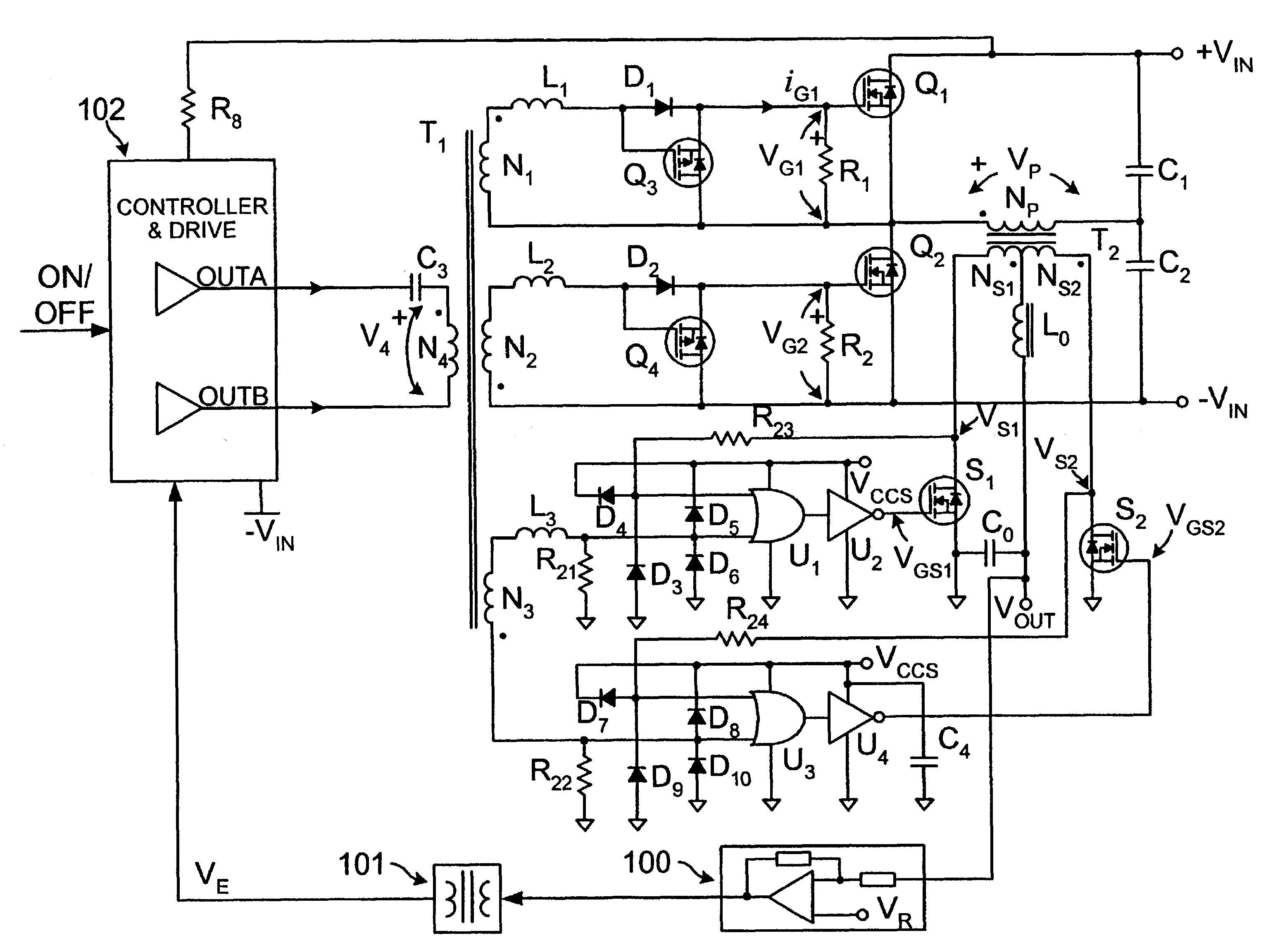
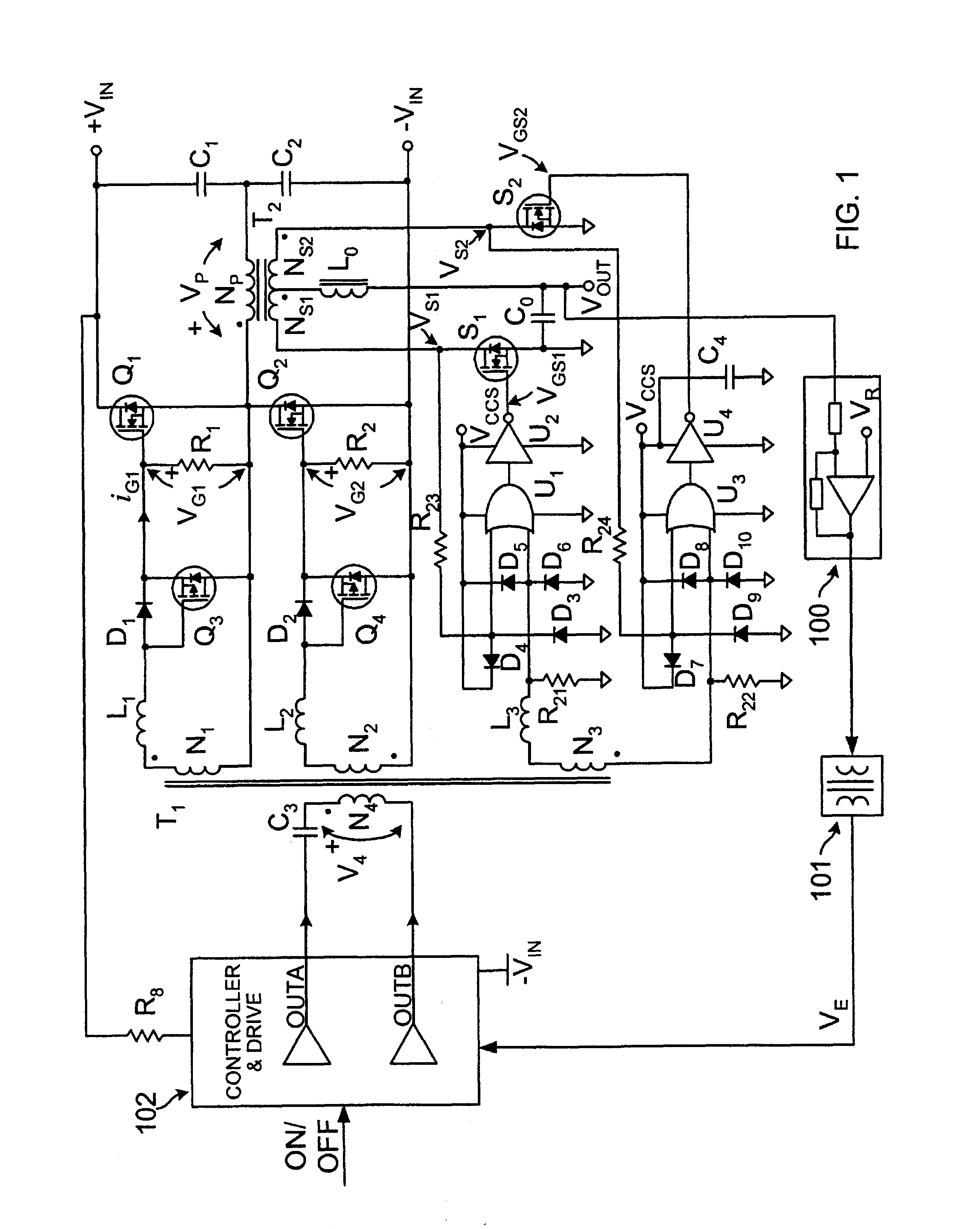
[0027]With reference now to FIG. 1, there is shown an embodiment of the invention using a half-bridge converter. Primary switches Q1, Q2 (also called primary controllable power switches), synchronous rectifiers S1 and S2, capacitors C1, C2 and C0, power isolation transformer T2 and inductor L0 form a half-bridge dc-to-dc converter. The invention could also be embodied in other topologies including ac-to-dc, dc-to-ac and others. Input voltage VIN is split with capacitors C1 and C2. One side of primary winding NP of transformer T2 is connected to the common connection of capacitors C1 and C2 while the second end is connected to the common point of switches Q1 and Q2. Two secondary windings NS1 and NS2 are preferably identical and are connected in series. The common point of these windings NS1 and NS2 is connected to one end of output inductor L0, and the second end of inductor L0 is connected to capacitor C0 that is connected across the output of the converter. The second end of windi...


PUM


Abstract

A drive transformer and associated circuitry for providing power and appropriate delays to primary switches and synchronous rectifiers in switch-mode power converters. The circuitry takes advantage of the leakage inductances of the drive transformer windings as well as the input capacitance of the primary switches (MOSFETs) to provide the necessary delays. No separate circuitry is needed to provide such delays, thereby providing reliability. Exemplary embodiments further disclose means to disable or enable the primary winding from a condition sensed on the secondary side even with a control and feedback circuit located on the secondary side.

Description

CROSS REFERENCE TO RELATED APPLICATION[0001]This is a non-provisional application based on provisional application Ser. No. 60 / 265,714 filed Feb. 1, 2001.BACKGROUND[0002]1. Field of the Invention[0003]This invention relates generally to switch-mode power converters and more particularly it provides a simple drive circuit with an enable function providing isolation and having high performance in topologies using synchronous rectification.[0004]2. Background Discussion[0005]A switch-mode power converter is a circuit that uses an inductor, a transformer, or a capacitor, or some combination, as energy storage elements to transfer energy from an input source to an output load in discrete pulses. Additional circuitry is added to maintain a constant voltage within the load limits of the circuit. The basic circuit can be configured to step up (boost), step down (buck), or invert output voltage with respect to input voltage. Using a transformer allows the output voltage to be electrically is...

Claims


Application Information

Patent Timeline
IPC IPC(8): H02M3/335H02H7/122H02M1/088H02M1/38
CPCH02M1/088H02M3/33592H02M1/38Y02B70/1475Y02B70/10
Inventor BRKOVIC, MILLVOJE S.
Owner BEL POWER SOLUTIONS INC
Why Eureka
Try Eureka