Optical disk

Inactive Publication Date: 2006-09-05
FUJITSU LTD +1
View PDF15 Cites 12 Cited by
  • Summary
  • Abstract
  • Description
  • Claims
  • Application Information

AI Technical Summary

Benefits of technology

[0015]The present invention provides an optical disk comprising: at least a rewritable region and a read-only data region, wherein the rewritable region includes a plurality of groove tracks and a plurality of land tracks, the read-only data region includes a plurality of groove tracks and a

Problems solved by technology

In this case, the capacity of the optical disk is inefficiently used by providing the flat region.
However, since the concavo-convex pits are formed in a flat surface which has no grooves, an optical head is likely to mistakenly detect the track pitch when the optical head seeks the flat surface, and there is a risk in that desired control can not be performed.
However, since the resolution for reading the above-described concavo-convex pits is not increased by this technology, data which are written by using the concavo-convex pits having the same pitch as the magneto-optical marks along the circumference of the disk (in the track direction) could not be read at high resolution.
It

Method used


Image

  • Optical disk
  • Optical disk
  • Optical disk

Examples


first embodiment

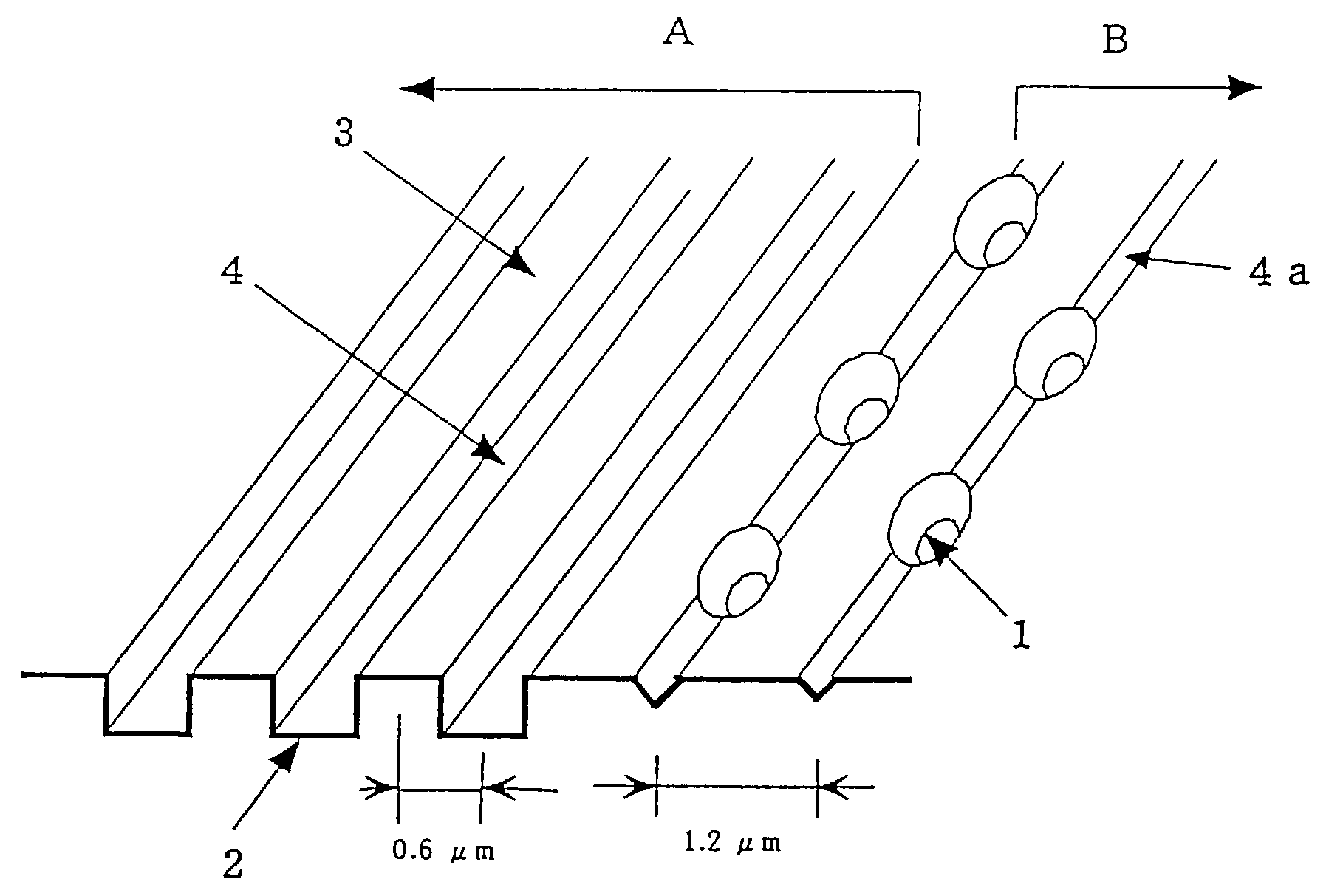
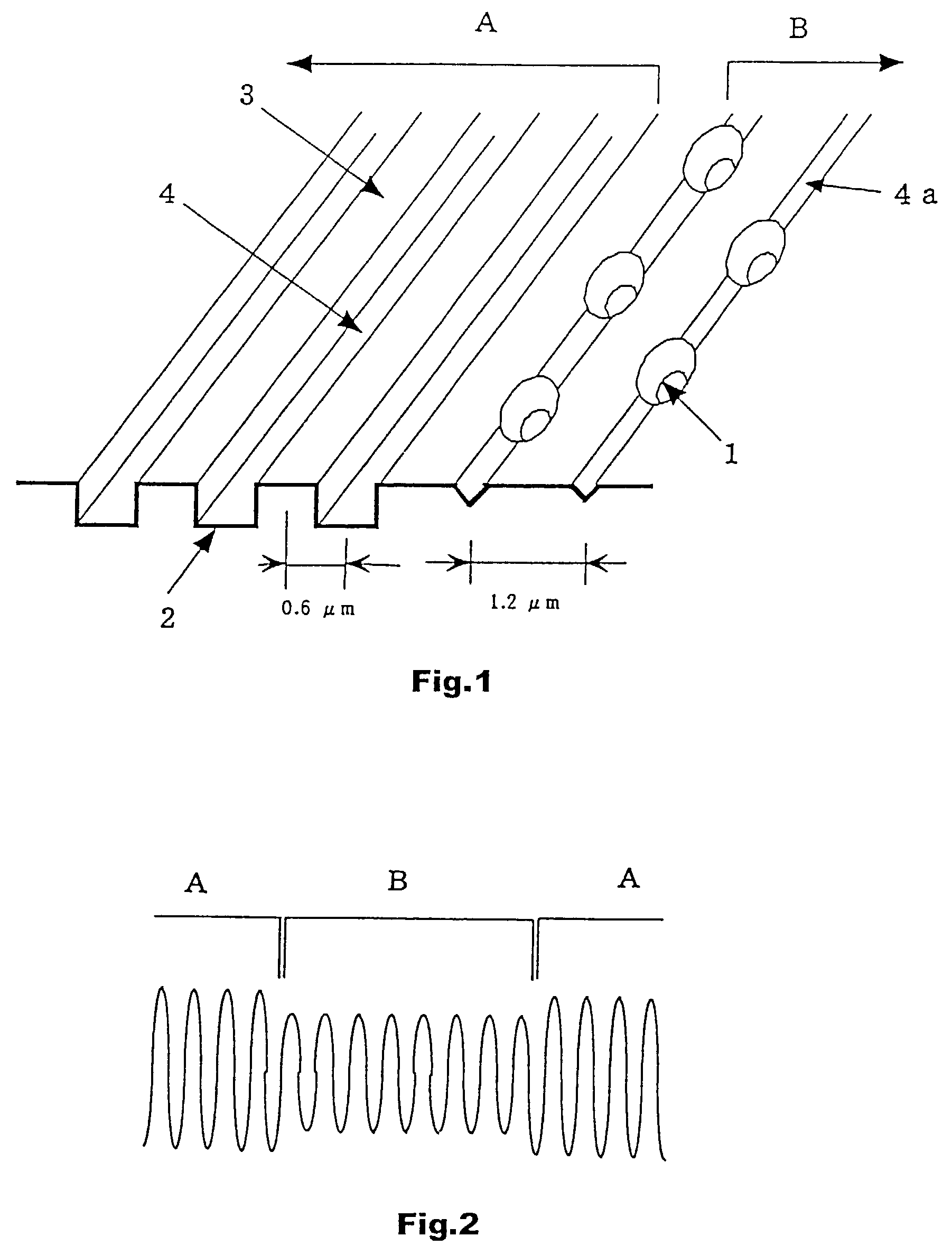
[0046]FIG. 1 is a schematic perspective view of an optical disk according to a first embodiment of the present invention. The optical disk shown in FIG. 1 is provided with a land track / groove track region A which is a rewritable region and a control data region B as a read-only data region adjacent to the region A, the control data region B being provided with concavo-convex pits 1 representing control data. The optical disk shown in FIG. 1 is provided with a magnetic super-resolution magneto-optical recording film 2, for example, which includes three layers of GdFeCo / GdFeCoSi / TbFeCo deposited on a polycarbonate substrate.

[0047]The track pitch of the land track / groove track region A is 0.6 μm. The widths of a land 3 and a groove 4 are substantially the same as each other, which is 0.6 μm. The depth of the groove 4 is 55 nm.

[0048]Indented pits 1 formed in the control data region B each have an aperture width of 0.4 μm and a depth of 55 nm. Grooves 4a formed in the region B each have ...

second embodiment

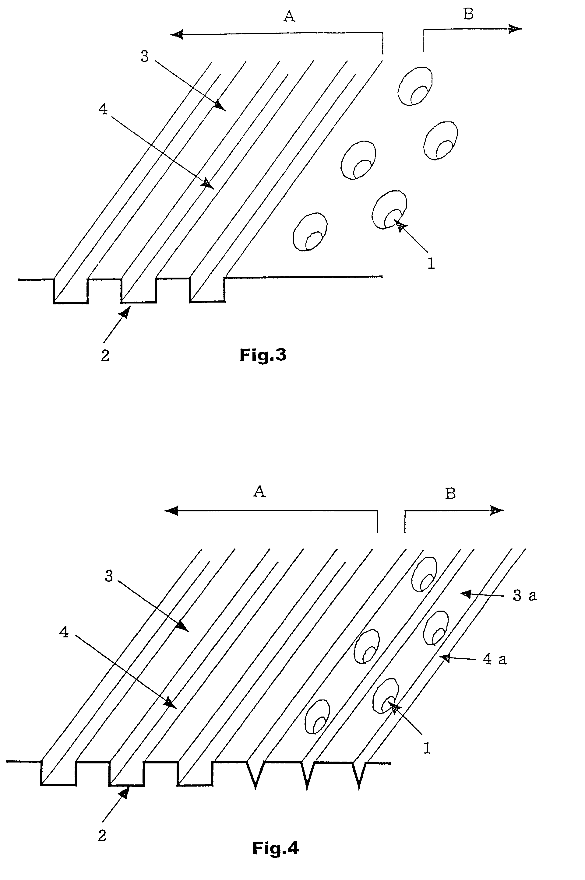
[0051]FIG. 4 shows an optical disk according to a second embodiment of the present invention. This optical disk is provided with concavo-convex pits 1 in lands 3a disposed in a control data region B. Grooves 4a formed in the control data region B each have an aperture width of 0.4 μm and a depth of 55 nm. The concavo-convex pits 1 each have a width of 0.4 μm and a depth of 50 nm. Other configuration is the same as that of the optical disk shown in FIG. 1. In the optical disk shown in FIG. 4, excellent seeking is possible, as in the optical disk shown in FIG. 1.

third embodiment

[0052]FIGS. 5(a) and 5(b) show an optical disk according to a third embodiment of the present invention. The optical disk shown in these drawings has the same configuration as that of the optical disk shown in FIG. 1 except that concavo-convex pits are provided both in lands 3a and grooves 4a which are formed in a control data region B. In FIGS. 5(a) and 5(b), numeral 5 denotes header data regions, numeral 6 denotes buffer tracks, and numeral 7 denotes control data. The header data regions 5 and the control data regions 7 include concavo-convex pit rows each including a plurality of concavo-convex pits, which are shown in a simplified form in the drawings.

[0053]In FIG. 5(a), in the seek direction, pit rows 7 each including a plurality of the concavo-convex pits formed in the lands 3a and the pit rows 7 each including a plurality of the concavo-convex pits formed in the grooves 4a are alternately disposed in the track direction with the header data regions 5 therebetween. That is, in...


PUM


Abstract

The present invention provides an optical disk comprising: at least a rewritable region and a read-only data region, wherein the rewritable region includes a plurality of groove tracks and a plurality of land tracks, the read-only data region includes a plurality of groove tracks and a plurality of land tracks, read-only data comprising control data are written as concavo-convex pits to the groove tracks and/or the land tracks in the read-only data region, and the width of each groove in the read-only data region is smaller than that of each groove in the rewritable region. According to the first optical disk of the present invention, the area of rewritable regions for users can be ensured as broadly as possible failing to deteriorate the high-speed performance of the system.

Description

CROSS-REFERENCE TO RELATED APPLICATION[0001]This application is related to international application No. PCT / JP00 / 01156 filed on Feb. 28, 2000, whose priority is claimed under 35 USC §120, the disclosure of which is incorporated by reference in its entirety.TECHNICAL FIELD[0002]The present invention relates to optical disks. In particular, the present invention relates to an optical disk provided with a read-only data region.BACKGROUND ART[0003]Rewritable and removable optical disks have been widely used as file memories for personal computers. Hitherto, various technologies for increasing the recording density of the optical disks have been developed.[0004]Methods for recording marks (mark position recording / mark length recording), methods for dividing regions into sectors (Constant Angular Velocity / Zone Constant Angular Velocity: CAV / ZCAV), and the like are known as methods for increasing the recording density. Other than these methods, a method for reducing the track pitch or the...

Claims


Application Information

Patent Timeline
IPC IPC(8): G11B7/24G11B7/007G11B7/013G11B7/24035G11B7/24076G11B7/24079G11B7/24091G11B7/24097G11B7/30G11B20/12
CPCG11B7/00718G11B7/24085G11B7/24079G11B2020/1259
Inventor MORIBE, MINEOKURODA, SUMIOIIDA, KOICHITAKEMOTO, HIROYUKI
Owner FUJITSU LTD
Why Eureka
Try Eureka