Active rotational balancing system for orbital sanders

a rotational balance and orbital sander technology, applied in the field of dynamically compensated electrically or pneumatically powered hand tools, can solve the problem of low vibration level of handgrips, and achieve the effect of greatly reducing the vibration level of handgrips, and reducing the interaction of rotational force with handgrips

Inactive Publication Date: 2006-09-12
BERG FREDERIC P
View PDF11 Cites 9 Cited by
  • Summary
  • Abstract
  • Description
  • Claims
  • Application Information

AI Technical Summary

Benefits of technology

[0009]An active dynamic rotational balancing system corrects for both the radial imbalance forces and the operator pushing force generated by orbital sander operation. When these corrections are made, all rotational force interactions with the handgrip are greatly reduced; this results in lower handgrip vibration levels.
[0010]A system uses a programmable microcontroller to implement the feedback control algorithm and to operate two miniature stepper motors that reposition correction masses. Two accelerometers integrated into the bearing mounts provide feedback information. The programmable microcontroller compensates for a phase shift difference with reference to an optical sensor. Each stepper motor operates a lead screw to move correction masses radially in the two planes of imbalance to correct for both the radial imbalance forces and for the operator pushing force generated by orbital sander operation. When the stepper motor compensates for them, all rotational force interactions vibrating the handgrips are greatly reduced.

Problems solved by technology

When these corrections are made, all rotational force interactions with the handgrip are greatly reduced; this results in lower handgrip vibration levels.

Method used


Image

  • Active rotational balancing system for orbital sanders
  • Active rotational balancing system for orbital sanders
  • Active rotational balancing system for orbital sanders

Examples


Embodiment Construction

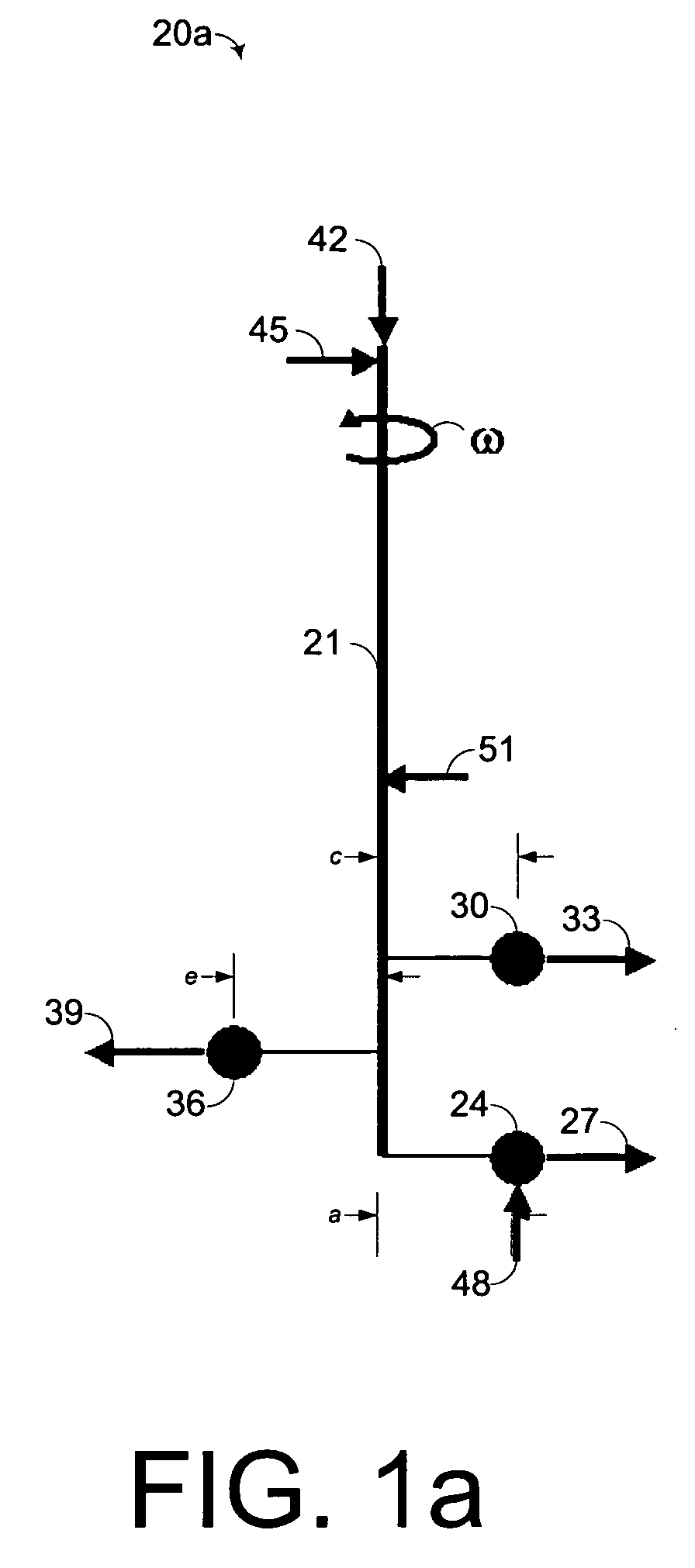
[0021]Referring to FIG. 1a, a force diagram 20 aids in the description and analysis of the forces causing vibration in an orbital sander. In this diagram the forces are all coplanar. A motor shaft 21 spinning about that axis at a rotation speed of ω provides a frame of reference. The motor shaft 21 is the principal moving part of the orbital sander and drives the operational components including the sanding pad with attached sandpaper. For purposes of analysis the sanding pad assembly may be fairly represented by a point mass located at a center of the constituent mass. The motor shaft 21, can be assumed symmetrical around the motor shaft axis and with homogeneous density, thereby not contributing to any imbalance in the system.

[0022]The mass of the sanding pad assembly with sandpaper can be represented by mass 24 at distance a from a motor shaft axis 21 of rotation. At rotational speed ω, the mass 24 imparts a rotational force 27 on the motor shaft axis 21, that is the product of r...


PUM


Abstract

A system for active dynamic balancing of a rotating tool driven by a motor having a shaft supported by a first and second bearing on opposing sides of the motor includes an acceleration sensing assembly configured to sense radial accelerations on the shaft producing an acceleration signal indicative of the radial accelerations. A correcting mass assembly is configured to rotate with the shaft and to move at least one mass radially to the shaft responsive to a correcting signal. A controller is configured to receive the acceleration signal generating a correcting signal by means of a closed loop iterative algorithm.

Description

FIELD OF THE INVENTION[0001]This invention relates generally to electrically or pneumatically powered hand tools and, more specifically, to dynamically compensated electrically or pneumatically powered hand tools.BACKGROUND OF THE INVENTION[0002]Sanders are generally described by the characteristic motion by which drive their abrasive; sanders may be orbital, in-line, disk, or belt sanders. In-line, disk, and belt sanders gouge distinct abrading marks on the surface of the workpiece, by the cumulative effects of the abrading medium as it travels in the same direction. To produce a suitable finish, another tool, such as an orbital sander later must remove the resultant abrasion marks. Orbital sanders produce a more random abrading pattern, therefore, a more uniform and desirable surface finish. In general, using belt, inline, and disk sanders is limited to aggressive surface abrading of the workpiece surface.[0003]Orbital sanders drive a sanding pad in an eccentric orbit around the m...

Claims


Application Information

Patent Timeline
Patent Type & Authority Patents(United States)
IPC IPC(8): B24B49/00
CPCB24B23/03B24B41/042B24B41/007
Inventor BERG, FREDERIC P.
Owner BERG FREDERIC P
Why Eureka
Try Eureka