
Carburetor with intermediate throttle valve blocking position

a technology of intermediate throttle valve and carburetor, which is applied in the direction of fuel gas production, gas purification by liquid washing, secondary air addition to fuel, etc., can solve the problem of not allowing flow through the second channel

Inactive Publication Date: 2006-09-12
HOMELITE TECH
View PDF24 Cites 18 Cited by
  • Summary
  • Abstract
  • Description
  • Claims
  • Application Information

AI Technical Summary

Benefits of technology

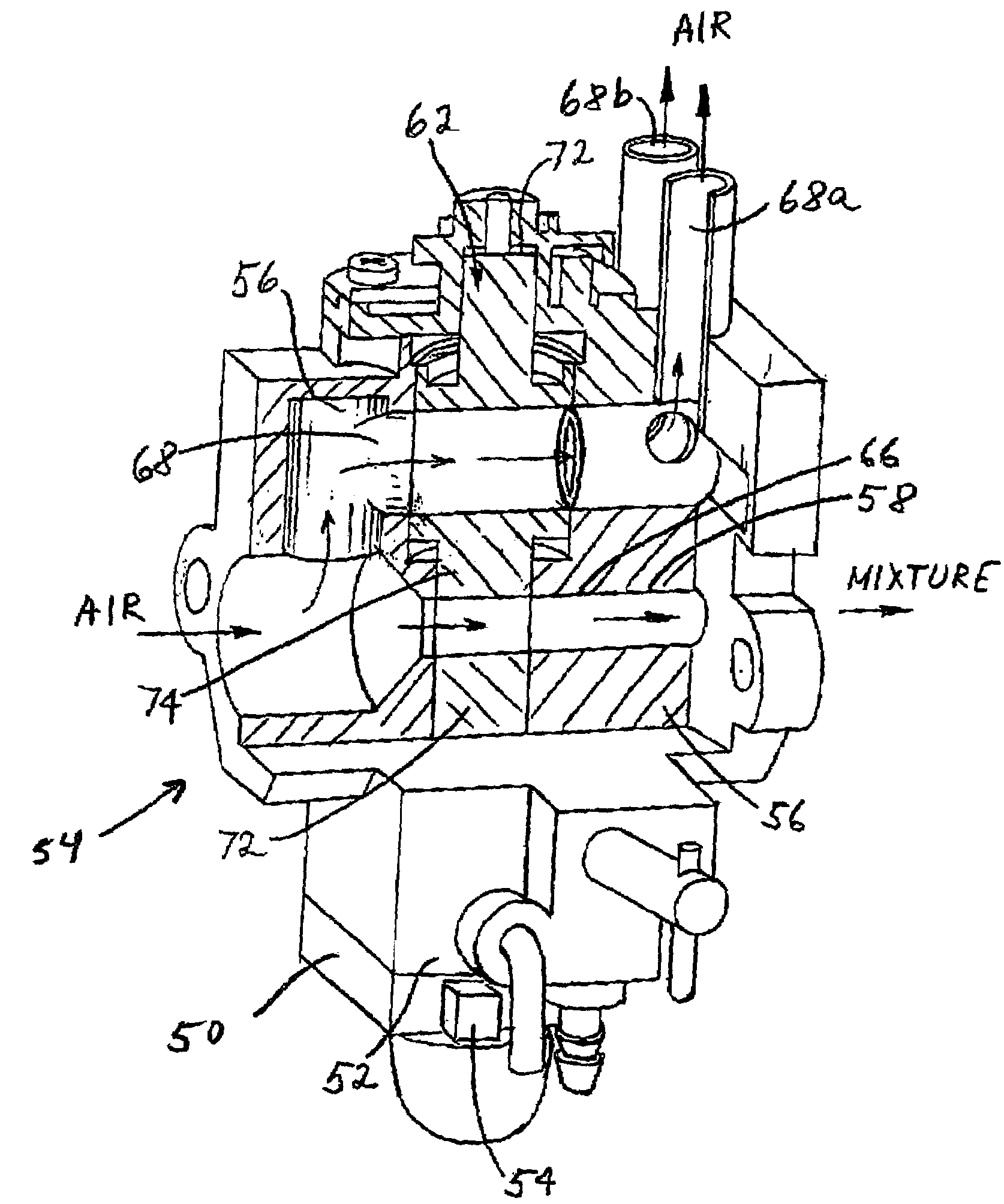
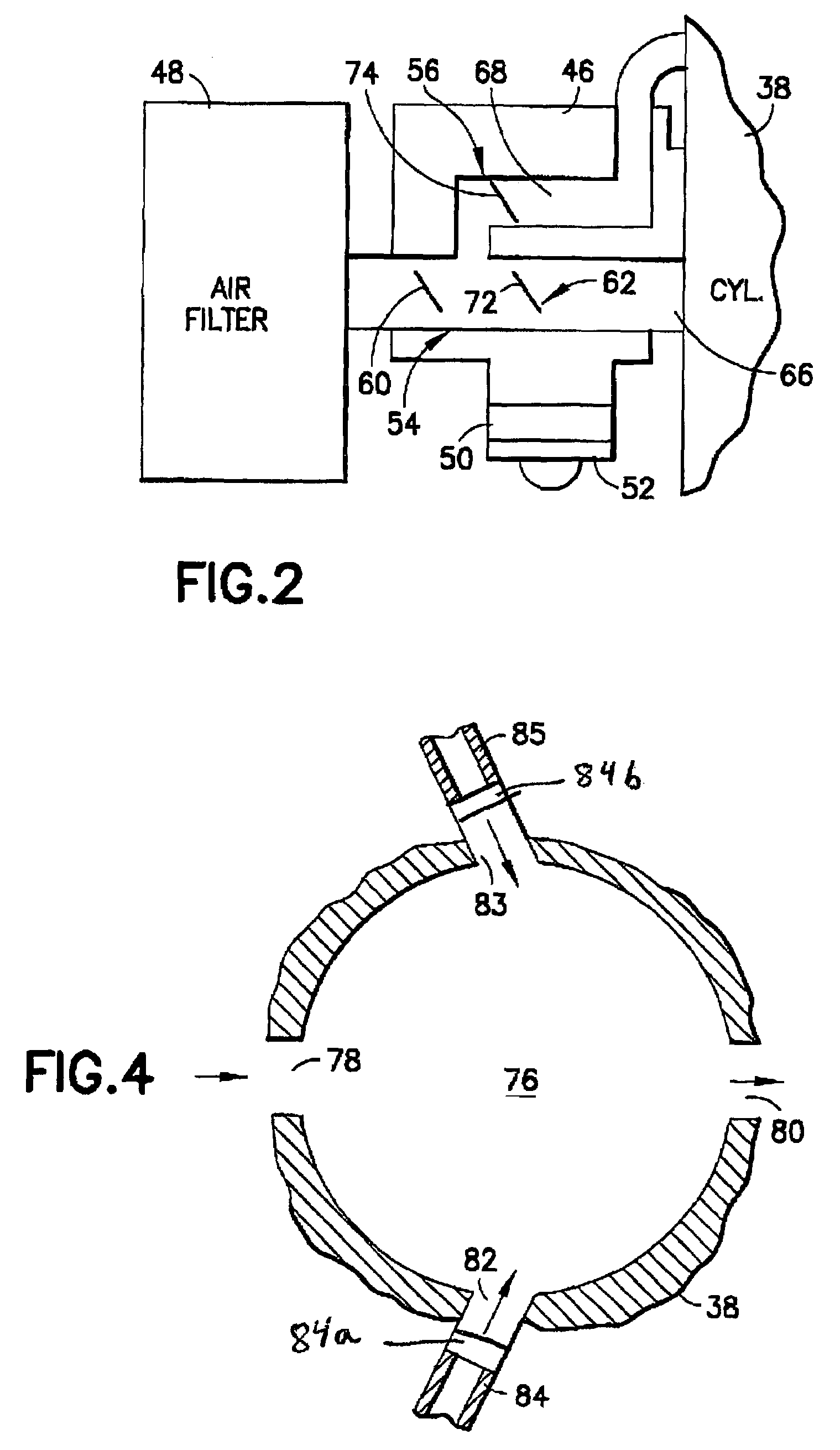
[0008]In accordance with one method of the present invention, a method of supplying air and an air/fuel mixture through a carburetor in an internal combustion engine is provided comprising steps of locating a throttle valve assembly of the carburetor at an idle position, wherein air is allowed to flow through an air channel of the carburetor through an air bleed hole in the throttle valve assembly, and wherein the air/fuel mixture is allowed to flow ...

Problems solved by technology

The air bleed hole allows flow through the second channel at the first idle position, but does not allow flow through the second channel when the second valve section is at the intermediate closed position.

Method used


Image

  • Carburetor with intermediate throttle valve blocking position
  • Carburetor with intermediate throttle valve blocking position
  • Carburetor with intermediate throttle valve blocking position

Examples


Embodiment Construction

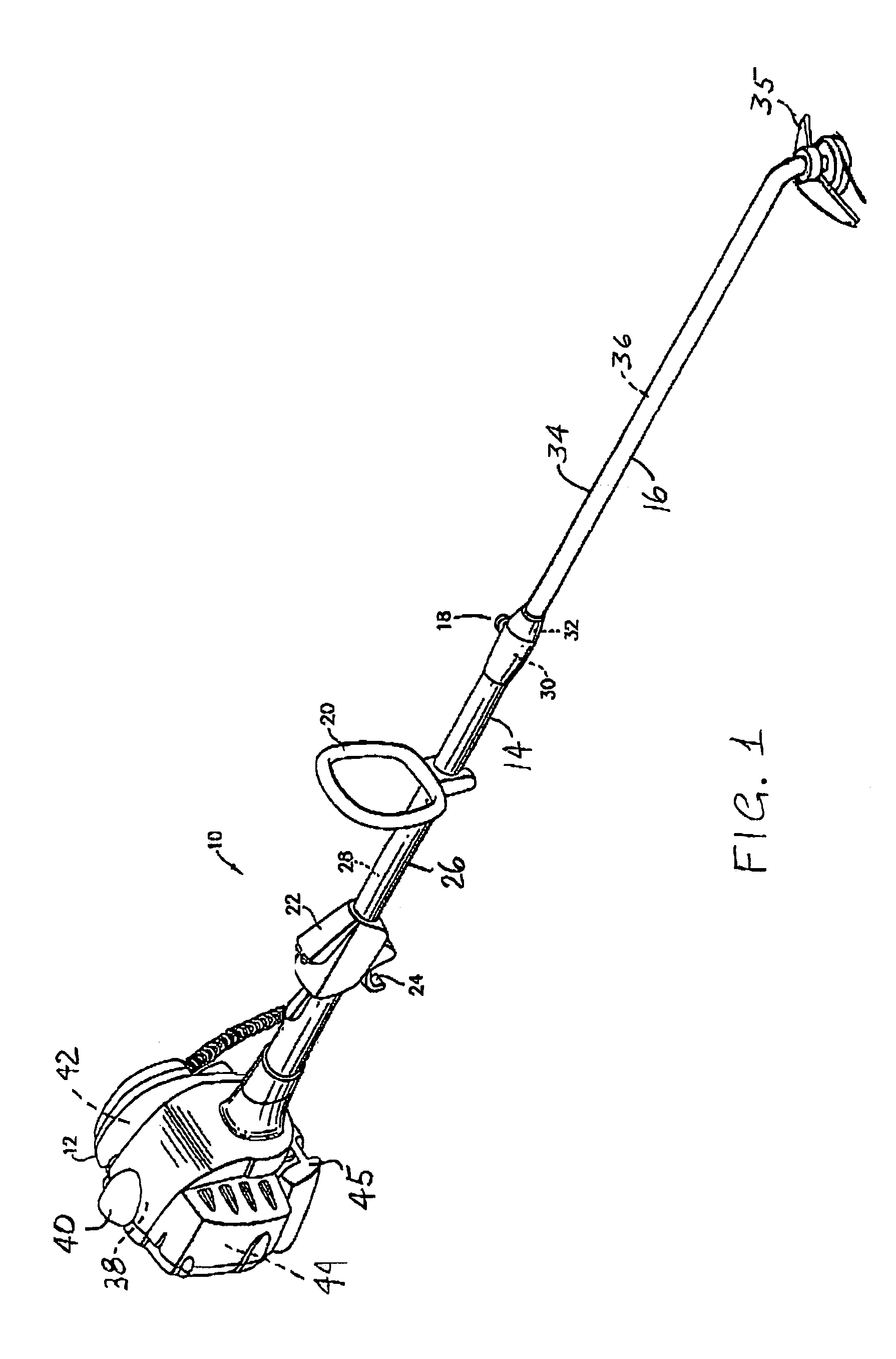
[0023]Referring to FIG. 1, there is shown a perspective view of a motorized power tool 10 incorporating features of the present invention. Although the present invention will be described with reference to the exemplary embodiments shown in the drawings, it should be understood that the present invention can be embodied in many alternate forms of embodiments. In addition, any suitable size, shape or type of elements or materials could be used.

[0024]The power tool 10 in the embodiment shown is a string trimmer. However, in alternate embodiments, features of the present invention could be used in any suitable type of power tool, such as a hedge trimmer, a chain saw, a blower / vac, etc. In addition, features of the present invention could be used in any suitable type of two stroke internal combustion engine or carburetor for such an engine.

[0025]The power tool 10 generally comprises a motor 12, a first boom member 14, a second boom member 16 and a coupling system 18. However, in alterna...


PUM

PropertyMeasurementUnit
Fractionaaaaaaaaaa
Flow rateaaaaaaaaaa

Abstract

A carburetor including a frame having a first air / fuel channel and a second air channel; and a throttle valve assembly connected to the frame and having two valve sections. Each valve section is located in a respective one of the channels. A second one of the valve sections has an air bleed hole therethrough. The second valve section is movable relative to the frame from a first idle position to a second intermediate closed position and then to a third open position at a wide open throttle (WOT). The air bleed hole allows flow through the second channel at the first idle position, but does not allow flow through the second channel when the second valve section is at the second intermediate closed position.

Description

BACKGROUND OF THE INVENTION[0001]1. Field of the Invention[0002]The present invention relates to internal combustion engines and, more particularly, to a carburetor.[0003]2. Brief Description of Prior Developments[0004]U.S. Pat. No. 6,347,787 discloses a carburetor with two passages and two valves. The valves are connected by gears for different motions relative to each other. U.S. Pat. No. 6,216,650 discloses a stratified engine with a carburetor and an ON / OFF valve. U.S. Pat. No. 6,349,925 discloses a carburetor with an air valve shaft and a throttle valve shaft movably coupled to each other.[0005]It has been observed that when a large size main jet is used in a double barrel carburetor, the hydrocarbon emission is very high. When a small size jet or the needle is adjusted for low emission at idle, the acceleration may become unsatisfactory. There is a desire to provide a carburetor for a stratified engine which can allow air to flow through an air channel at idle and at wide open...

Claims


Application Information

Patent Timeline
IPC IPC(8): F02M7/26F02M23/09F02M23/03
CPCF02M7/26F02M23/03Y10S261/01Y02T10/146Y02T10/12
Inventor MAVINAHALLY, NAGESH S.
Owner HOMELITE TECH
Learn More