Platen mounted post mold cooling apparatus and method

a cooling apparatus and plate mold technology, applied in the field of methods and apparatus for cooling molded plastic objects, can solve the problems of affecting the clarity of the final product, touching parts to weld together, surface softening and being easily marred, etc., to achieve accurate control of motion and stop points, reduce vibration motion and consequential carrier-alignment issues, and simplify the effect of robot structure and function

Active Publication Date: 2006-09-12
HUSKY INJECTION MOLDING SYST LTD
View PDF16 Cites 42 Cited by
  • Summary
  • Abstract
  • Description
  • Claims
  • Application Information

AI Technical Summary

Benefits of technology

[0065]One advantage of the present invention is that the multi-position plate 37 is more accurately controlled in its motions and stopping points so that the vibration motions and consequential carrier-alignment issues are minimized. Further, by transferring the parts to the platen mounted treatment A device 39, the robot structure and function are simplified by not having a high performance drive means for the rotational axis at the end of the Y beam, thus saving weight and cost on the carriage. Additionally, by mounting the treatment A device 39 on the movable platen 41, this location moves the outboard position of the multi-position take off plate 37 closer inboard, thereby shortening the Z beam and reducing the overall width / footprint of the machine. Also, mounting the treatment A device 39 on the movable platen 41 saves the cost of providing an independent motion and guiding means for the device 39 to engage and disengage the parts in the carriers 38, these items already being providing by the movable platen itself.
[0066]FIGS. 12 and 13 show a second embodiment of the invention in which two different treatment processes are performed on the parts while they are in their carriers. Co-pending U.S. application Ser. No. 10 / 147,360 filed May 17, 2002 discloses a system for temperature conditioning the interior of freshly molded parts by using a treatment A device and / or by using a treatment B device. The latter inserts a cooling tube with a sealing means so that pressurized cooling fluid introduced into the interior of the part via the tube is temporarily contained therein and pressurizes the part causing it to remain in contact with the inside surface of its carrier to maintain optimum heat transfer to the carrier by intimate contact and thereby resisting the shrinkage of the part as it cools, which, if unchecked, causes the part to lose contact with the inside surface of the carrier.
[0067]FIG. 12 shows an extended treatment A plate 100 on which an additional two rows of cooling pin / carriers 101 and 102 have been mounted. Four rows of treatment B tubes 103, 104, 105 and 106 are shown in between the rows of cooling pin / carriers 112. This example of tube layout is one so-called multiple treatment configuration suitable for operation with a three position multi-position take out plate 107; however, other combinations of treatment A tubes and treatment B tubes is possible.5. The Process of the Second Embodiment
[0068]FIGS. 13a,13b,13c; 14a,14b,14c; and 15a,15b,15c, in combination, show a complete sequence of operations of the multiple treatment device and multi-position take out plate to treat the parts 109 in the carriers 108. FIG. 13a shows the multi-position take out plate 107 in the first of its three outboard positions in which freshly molded part 110 is aligned with treatment B tube 111 on the multiple treatment plate 100. All the carriers are carrying parts. Each of the freshly molded parts 110 is aligned similarly with a corresponding treatment B tube. FIG. 13b shows the multiple treatment plate 100 engaged with the parts allowing cooling treatment to take place. The treatment B tubes pressurize the interior of the parts with cooling fluid while the treatment A tubes project cooling fluid to un-pressurized parts allowing the fluid to vent out of the open end of the parts. FIG. 13c shows the multiple treatment plate 100 disengaged from the carriers and selected parts being removed by those cooling pin / carriers 112 to which a vacuum has been applied. The parts being removed comprise the molding set that has been in the carriers the longest. These parts are subsequently ejected from the tubes, as previously explained.
[0069]FIG. 14a shows the second outboard position of the multi-position take out plate 107 in which the next molding shot of freshly molded parts are aligned with the same treatment B tubes 111. FIGS. 14b and 14c show the remaining steps in the portion of the complete sequence in which all the parts are treated, those parts treated by the treatment B pressurizing tubes in the previous step, 14a are now treated with treatment A cooling, and the parts that have been the longest in their carriers are removed.
[0070]FIG. 15a shows the third outboard position of the multi-position take out plate 107 in which the next, third molding shot of freshly molded parts are again aligned with the same treatment B tubes 111. FIGS. 15b and 15c show the remaining steps in which the parts that have been in the carriers for the previous two segments of the sequence receive a second treatment A treatment prior to being removed from their tubes as shown in FIG. 15c. Thus, in the complete sequence, the parts are treated three times before being removed from their carriers.

Problems solved by technology

In the case of PET preforms, some manufacturing defects are:Crystallinity: The resin recrystallizes due to the elevated temperature of the core resin not cooling quickly enough.
The white appearance of the crystals impairs the clarity of the final product and provides an area of potential weakness in a resultant blown product.Surface blemishes: The ejected performs, initially having solidified surfaces are reheated by the core material which causes the surface to soften and be easily marred.
Sometimes this surface reheating can be severe enough to cause touching parts to weld together.Geometric inaccuracies: Handling partly-cooled performs or attempting to further cool them in devices that do not maintain their geometric shape while their surfaces are reheated can cause the preform's round diameter to become oval shaped or the smooth surface to become wrinkled or non-linear.
However, this will cause the injection molding cycle to be lengthened, typically 25 seconds or longer, wherein the majority of this time would be used solely for cooling purposes.
However, these patent documents do not disclose cooling the interior of the parts.
However, there is no disclosure of mounting the frame and pins onto a moving platen to utilize the motion of the moving platen to insert and retract the pins with respect to the parts.
However, there is no disclosure of repeated or multiple cooling of the parts' interiors.
However, there is no disclosure of part cooling, either exterior or interior, while the parts are being transported by either plate.
However, there is no disclosure of any cooling treatment.
A number of disadvantages are present in the injection molding machine configuration described with respect to FIGS.
The inertia of the plate can cause it to vibrate when quickly being brought to rest in one of its stationary positions, and cycle time can be lost in waiting for motion oscillations to damp out sufficiently before attempting a part transfer or cooling tube insertion.
A second disadvantage in the injection molding machine configuration described above is that when unloading the carriers 24, the entire multi-position take off plate 23 must be rotated 90 degrees and back again quickly.
Again, because of the weight and inertia involved, a high-performance, high-cost actuation device must be used if the rotation is not to take too long, since the time taken for this motion is time unavailable for CoolJet™ treatment.
The ability to provide different treatments to the parts in these multiple events is not possible.
A third disadvantage is that the time available for treatment to be applied by the CoolJet™ device is reduced by the time it takes for the multi-position take off plate 23 to rotate to the horizontal position, eject selected parts and rotate back to the vertical position.

Method used


Image

  • Platen mounted post mold cooling apparatus and method
  • Platen mounted post mold cooling apparatus and method
  • Platen mounted post mold cooling apparatus and method

Examples


first embodiment

2. The Structure of the First Embodiment

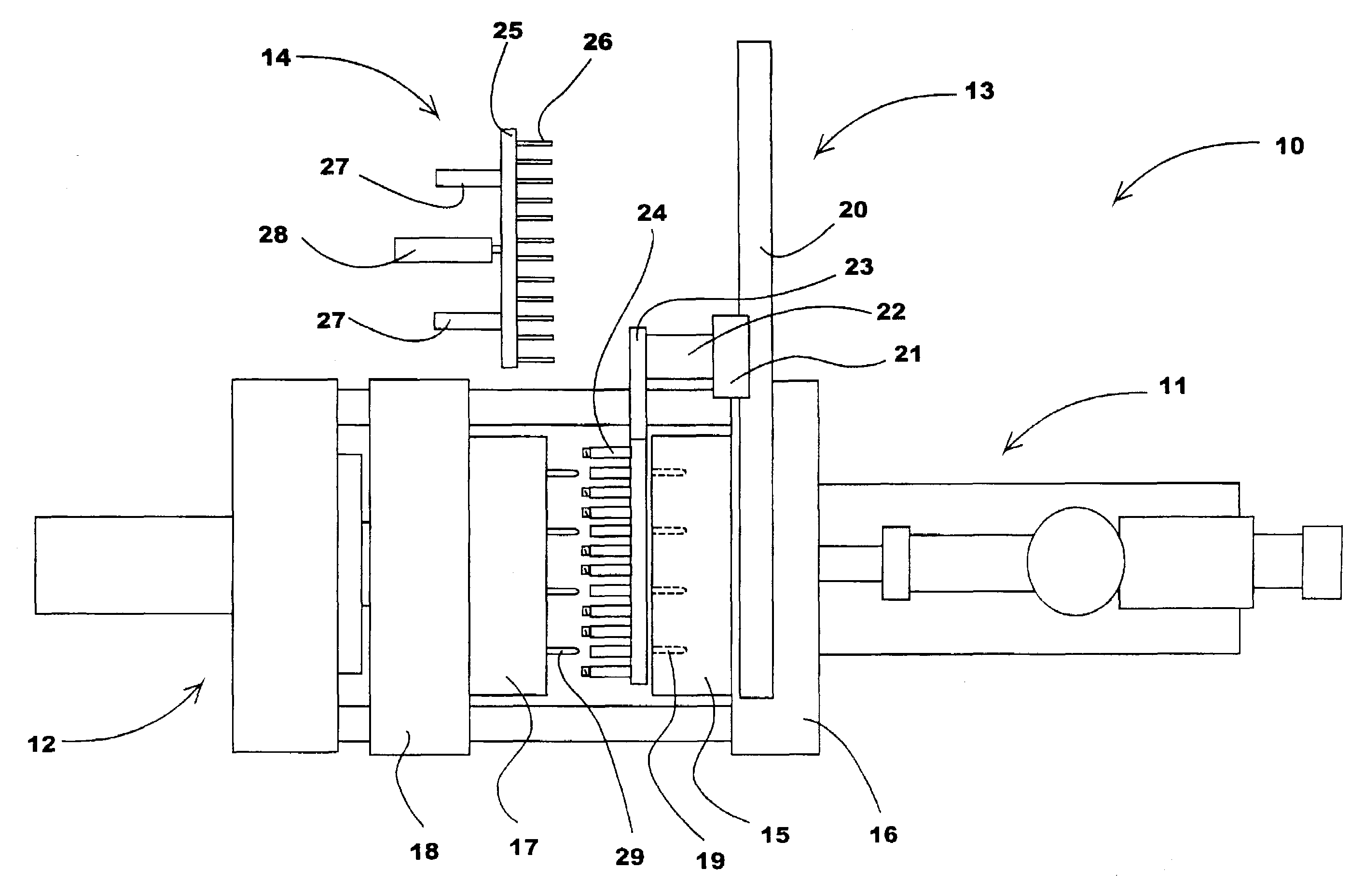
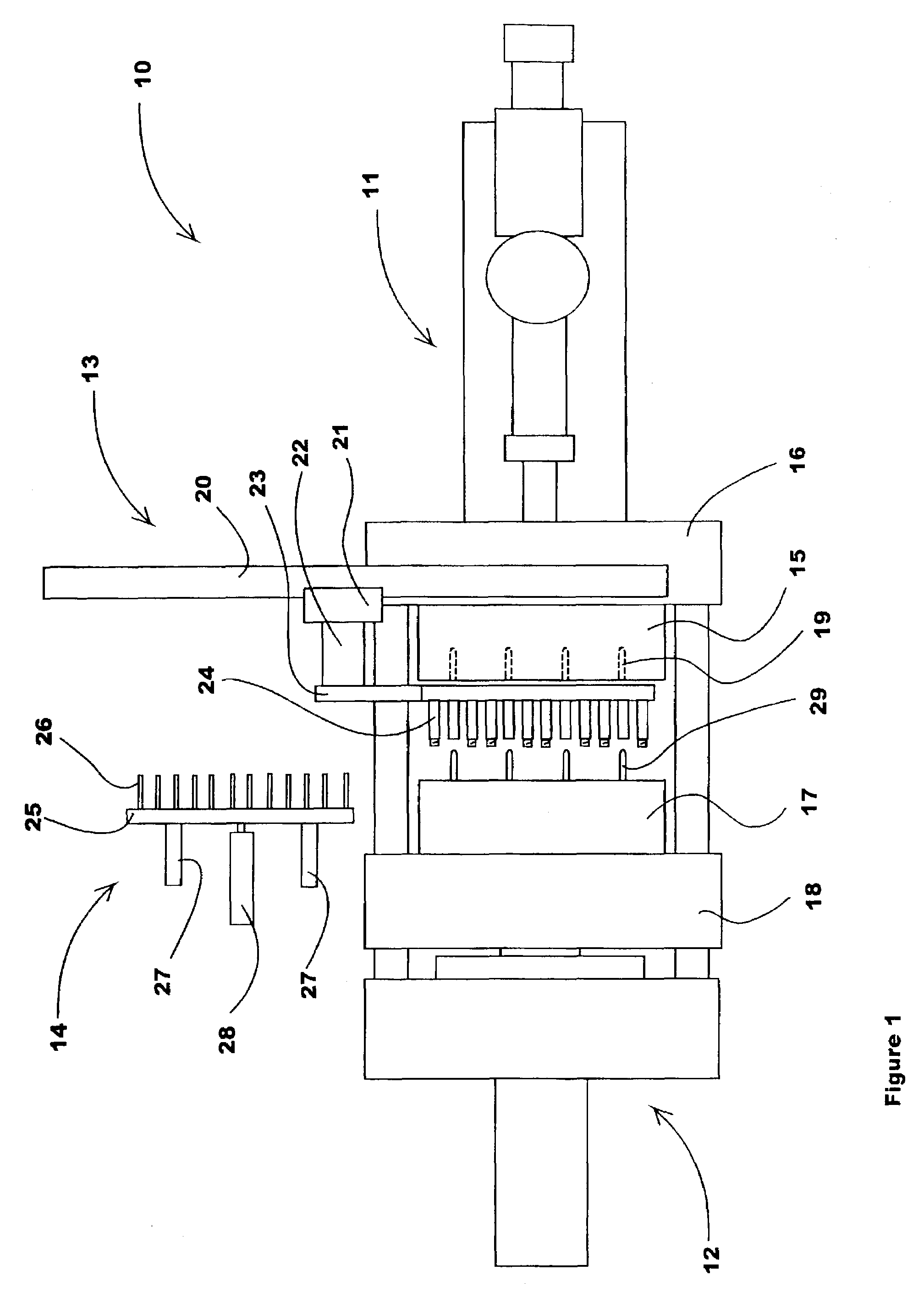
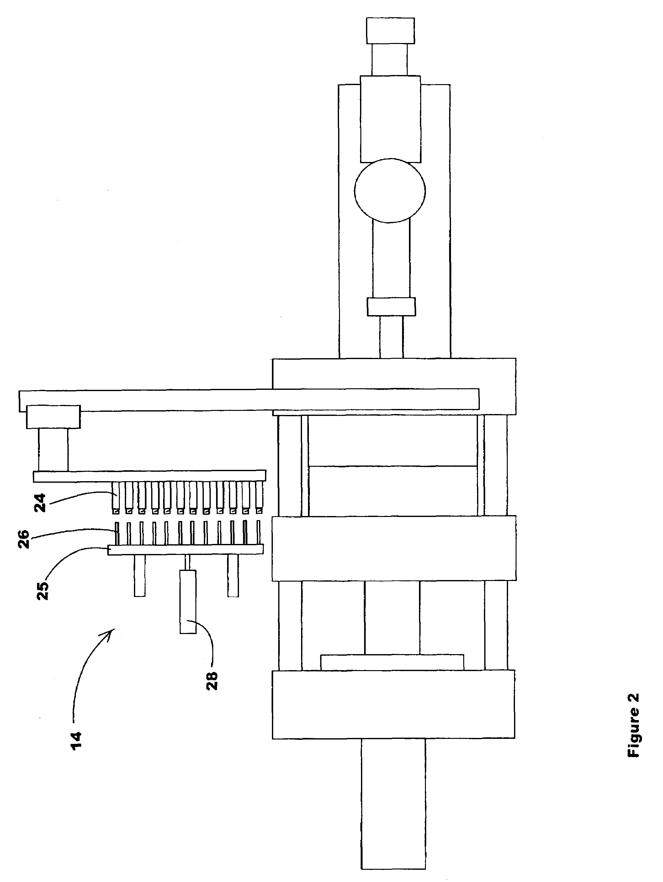
[0056]The first preferred embodiment of the present invention is shown in FIGS. 5–11. In those Figures, a robot Z beam 30 is attached to a preferably rigid mounting plate 31 that is preferably fastened to the top of a stationary platen 32. By mounting the Z beam 30 this way, a more rigid and less bendable structure is provided. The mounting plate 31 is contoured at 33, in the area immediately above the cavity half 35 to allow easy access into the machine for slings and handling devices to load and unload parts to / from the mold.

[0057]A robot carriage 34 is movably mounted on the Z beam 30 and is moved along the beam by a servo electric belt drive (actuator) system or functional equivalent (not shown). A Y beam 36 (see FIG. 8) is attached beneath the carriage 34 and contains service channels to supply a multi-position take off plate 37. Services such as cooling fluid, vacuum lines, and electric sensor or control circuits are routed directly thro...

second embodiment

4. The Structure of the Second Embodiment

[0066]FIGS. 12 and 13 show a second embodiment of the invention in which two different treatment processes are performed on the parts while they are in their carriers. Co-pending U.S. application Ser. No. 10 / 147,360 filed May 17, 2002 discloses a system for temperature conditioning the interior of freshly molded parts by using a treatment A device and / or by using a treatment B device. The latter inserts a cooling tube with a sealing means so that pressurized cooling fluid introduced into the interior of the part via the tube is temporarily contained therein and pressurizes the part causing it to remain in contact with the inside surface of its carrier to maintain optimum heat transfer to the carrier by intimate contact and thereby resisting the shrinkage of the part as it cools, which, if unchecked, causes the part to lose contact with the inside surface of the carrier.

[0067]FIG. 12 shows an extended treatment A plate 100 on which an addition...


PUM

PropertyMeasurementUnit
thicknessesaaaaaaaaaa
timeaaaaaaaaaa

Abstract

Platen-mounted, post-mold cooling apparatus and method includes structure and / or steps for handling molded parts in an injection molding machine having a fixed platen, a moving platen, a core half, and a cavity half. A take off device coupled to the fixed platen is configured to remove molded parts from either the core half or the cavity half. A cooling device coupled to the moving platen is configured to cool the molded parts carried by the take off device. Preferably, the take off device extracts the just molded parts from the mold's core half and then moves linearly outboard of the mold halves. The subsequent movement of the moving platen to close the mold in the next molding cycle causes the cooling device's pins to engage the molded parts in the take off device part carriers. When the moving platen opens again, the molded parts are extracted from the part carriers by the cooling device pins. When the moving platen is fully open, the cooling device is rotated to eject the cooled parts from the machine.

Description

BACKGROUND OF THE INVENTION[0001]1. Field of the Invention[0002]The present invention relates to a method and apparatus for cooling molded plastic articles after the molding operation is finished. In particular, the present invention relates to method and apparatus for an injection molding machine equipped with a post mold cooling (“PMC”) device mounted on a moving platen that cooperates with a multi-position robot take out plate to both cool the interior of the parts and to (preferably) selectively unload some of the molded part carriers on the multi-position take out plate. The method and apparatus are particularly well suited for cooling injection molded thermoplastic polyester polymer materials, such as polyethylene terephthalate (“PET”) preforms.[0003]2. Related Art[0004]A variety of post mold cooling methods are currently employed on injection molding machines to optimize the cooling of freshly molded plastic parts. Such methods include conductively cooling the parts while the...

Claims


Application Information

Patent Timeline
Patent Type & Authority Patents(United States)
IPC IPC(8): B29C45/42B29C45/78B29C45/72
CPCB29C45/42B29C45/7207B29B2911/14593B29K2105/253B29C2045/7214B29C2949/0811B29C2049/023B29C49/6427B29C45/72
Inventor DOMODOSSOLA, ROBERTARNOTT, ROBIN A.HUNTINGTON, CHRISTOPHER
Owner HUSKY INJECTION MOLDING SYST LTD
Why Eureka
Try Eureka