Control system and process for application of energy to airway walls and other mediums

Inactive Publication Date: 2006-09-12
BOSTON SCI SCIMED INC
View PDF4 Cites 229 Cited by
  • Summary
  • Abstract
  • Description
  • Claims
  • Application Information

AI Technical Summary

Benefits of technology

[0027]In yet another variation of the present invention, a process for transferring energy to a target medium using an energy delivery apparatus is provided. The energy delivery apparatus includes a flexible elongate body and a distal section wherein the distal section includes an expandable basket with at least one active region for transferring energy to the target medium. The energy delivery apparatus further has a temperature sensor located in the distal section for measuring a temperature (TM) of the target medium. The process comprises the following steps: setting

Problems solved by technology

Asthma is a disease in which bronchoconstriction, excessive mucus production, and inflammation and swelling of airways occur, causing widespread but variable airflow obstruction thereby making it difficult for the asthma sufferer to breathe.
The chronic nature of asthma can also lead to remodeling of the airway wall (i.e., structural changes such as thickening or edema) which can further affect the function of the airway wall and influence airway hyper-responsiveness.
It may, however, be impractical and not always helpful to avoid all potential stimuli.
High doses of corticosteroid anti-inflammatory drugs can have serious side effects that require careful manageme

Method used


Image

  • Control system and process for application of energy to airway walls and other mediums
  • Control system and process for application of energy to airway walls and other mediums
  • Control system and process for application of energy to airway walls and other mediums

Examples


examples

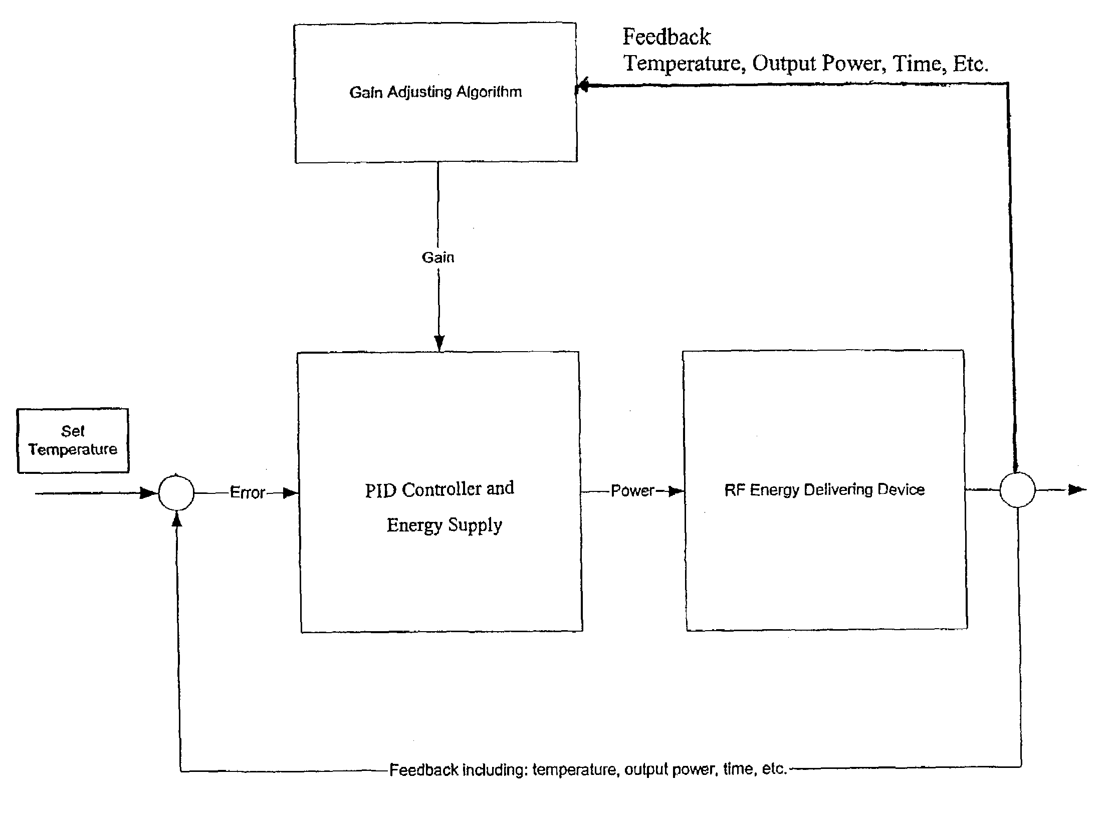
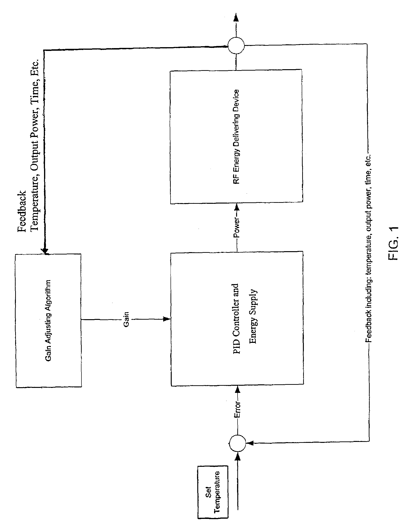
[0094]A system to treat airways in accordance with the present invention was built and tested in vivo on two canines. The system included an energy delivering apparatus having a distal basket. The basket included electrode legs and a temperature sensor mounted to one of the legs. The system also included a generator programmed to measure the temperature change per energy unit during the first half-second of treatment. A PID gain factor was adjusted depending on the measured tissue response. That is, the gain factor was adjusted based on the temperature change per joule output during the first half second. In general, this corresponds to a higher gain for less responsive tissue and lower gain for more responsive tissue.

[0095]After treating the test subjects with a general anesthetic, RF energy was delivered to target regions using an energy delivery device and generator as described above. In particular, energy activations were performed on all available intraparenchymal airways thre...


PUM


Abstract

The present invention includes a system for delivering energy to an airway wall of a lung comprising an energy delivering apparatus and a PID controller having one or more variable gain factors which are rest after energy deliver has begun. The energy delivering apparatus may include a flexible elongated member and a distal expandable basket having at least one electrode for transferring energy to the airway wall and at least one temperature sensor for measuring temperature. The PID controller determines a new power set point base on an error between a preset temperature and the measured temperature. The algorithm can be Pi+1=Pi+G(αei+βei−1+γei−2) where α, β and γ are preset values and α is from 1 to 2; βis from −1 to −2; and γ is from −0.5 to 0−5. In another variation, the controller is configured to shut down if various measured parameters are exceeded such as, for example, energy, impedance, temperature, temperature differences, activation time and combinations thereof. Methods for treating a target medium using a PID algorithm are also provided.

Description

CROSS REFERENCE TO RELATED APPLICATIONS[0001]This application is a continuation of PCT application number PCT / US / 01 / 32321, filed Oct. 17, 2001, and is a continuation-in-part of PCT / US / 00 / 28745, filed Oct. 17, 2000. The entirety of both applications are incorporated by reference herein.[0002]This application claims priority to International Application No. PCT / US 00 / 28745 filed Oct. 17, 2000 which is hereby incorporated by reference in its entirety.FIELD OF THE INVENTION[0003]This invention is related to systems for applying energy to lung airways and in particular, to a system and method for controlling the energy delivered to the airways using a PID algorithm to minimize error between a preset temperature and a measured temperature.BACKGROUND[0004]Various obstructive airway diseases have some reversible component. Examples include COPD and asthma. There are an estimated 10 million Americans afflicted with Asthma. Asthma is a disease in which bronchoconstriction, excessive mucus pro...

Claims


Application Information

Patent Timeline
IPC IPC(8): A61B18/18A61N1/06A61N1/40
CPCA61N1/06A61B18/14A61N1/40A61B2018/00541
Inventor BIGGS, MICHAELSTERN, ROGER A.DANEK, CHRISTOPHER JAMES
Owner BOSTON SCI SCIMED INC
Why Eureka
Try Eureka