
Protective sleeve assembly for a balloon catheter

a protective sleeve and catheter technology, applied in the field of catheters, can solve the problems of insufficient longitudinal force required to slide the outer sleeve over the inner sleeve, and achieve the effect of preventing or minimizing the damage to the balloon from the application and subsequent removal of the sleeve assembly

Active Publication Date: 2006-09-12
ABBOTT CARDIOVASCULAR
View PDF21 Cites 56 Cited by
  • Summary
  • Abstract
  • Description
  • Claims
  • Application Information

AI Technical Summary

Benefits of technology

[0007]This invention is directed to a protector sleeve assembly for a balloon catheter, configured for being removably disposed on at least a section of the catheter and preferably on at least the catheter non-inflated balloon prior to introduction of the catheter in a patient's body lumen, including a radially collapsible inner sleeve, and an outer sleeve with a tapered section. The inner sleeve has a relaxed configuration with an inner diameter greater than the outer diameter of the noninflated balloon, and a radially collapsed configuration with an inner diameter less than the relaxed inner diameter of the inner sleeve. The outer sleeve is slidably positioned on at least a portion of the inner sleeve and has a tapered first section with an inner diameter tapering towards a nontapered second section, the nontapered second section having a substantially uniform inner diameter less than an outer diameter of the relaxed inner sleeve and configured to hold the inner sleeve in the collapsed configuration. Consequently, the inner sleeve is in the collapsed configuration with the outer sleeve nontapered portion thereon, and the inner sleeve is in the relaxed configuration with the outer sleeve removed therefrom. One aspect of the invention is directed to a method of sheathing a balloon catheter, including positioning an inner and outer sleeve of a protector sleeve assembly of the invention on the at least a section of a balloon catheter. The protector sleeve assembly of the invention provides improved sheathing of the catheter balloon, in which the protector sleeve assembly is securely and removably disposed on the balloon, and damage to the balloon from the application and subsequent removal of the sleeve assembly is prevented or minimized.
[0012]The inner sleeve preferably has a length longer than the catheter balloon, so that the inner sleeve is disposed on at least the balloon and preferably on adjacent sections of the catheter shaft as well. The nontapered section of the outer sleeve preferably has a length not less than a working length of the balloon. In a presently preferred embodiment, the total length of the outer sleeve (i.e., tapered and nontapered sections) is less than the length of the inner sleeve, so that the operator can easily grasp the end of the inner sleeve down onto the catheter while sliding the outer sleeve over the inner sleeve. Consequently, the resistance caused by pushing the outer sleeve onto the inner sleeve does not cause the inner sleeve to slide and rub against the balloon.
[0014]The inner sleeve in contact with the balloon is not caused to move longitudinally relative to the balloon during application or removal of the sleeve assembly from the balloon. Thus, the surface of the balloon is not rubbed. As a result, in a balloon catheter with a balloon or stent coated with a coating such as a drug or lubricious coating, the coating is not removed therefrom during the application or removal of the sleeve assembly of the invention. Moreover, long sections of the balloon catheter can be securely sheathed, which is particularly advantageous with long balloons, such as those of peripheral balloon catheters, where friction makes it difficult to slide a tight sheath over the entire balloon. These and other advantages of the invention will become more apparent from the following detailed description of the invention and the accompanying exemplary drawings.

Problems solved by technology

Significantly, the longitudinal force required to slide the outer sleeve over the inner sleeve is not great enough to cause the inner sleeve to move longitudinally relative to the balloon (e.g., by buckling or compressing).

Method used


Image

  • Protective sleeve assembly for a balloon catheter
  • Protective sleeve assembly for a balloon catheter
  • Protective sleeve assembly for a balloon catheter

Examples


Embodiment Construction

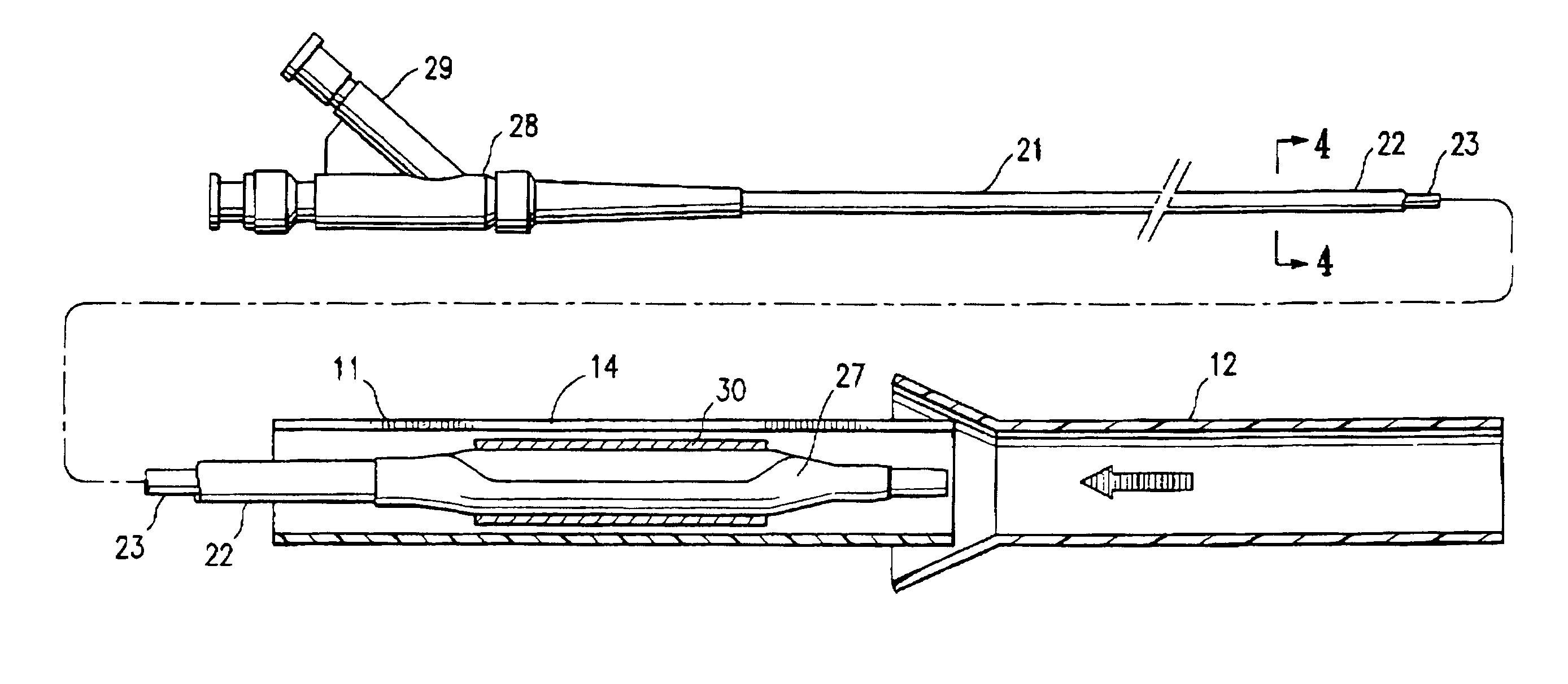
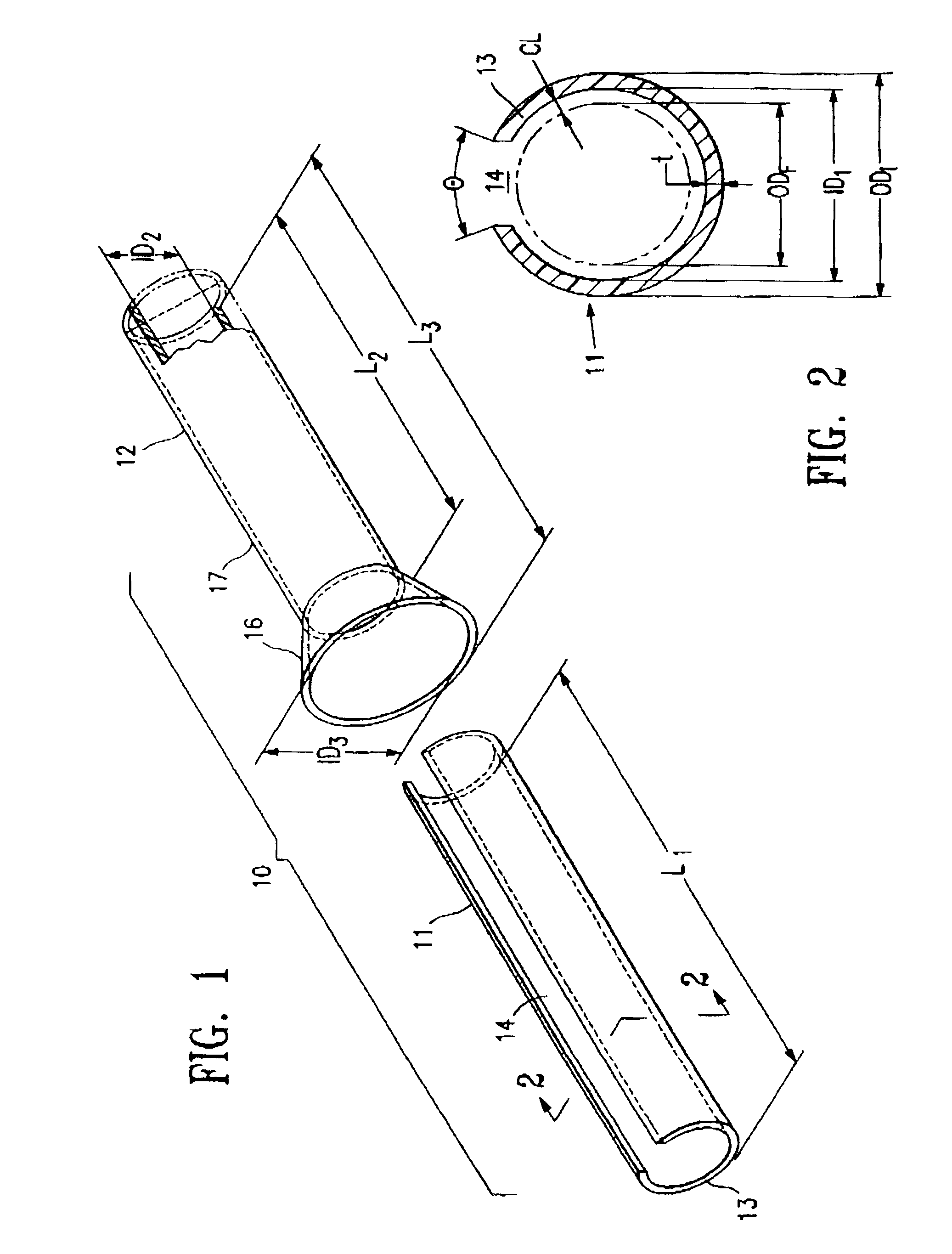
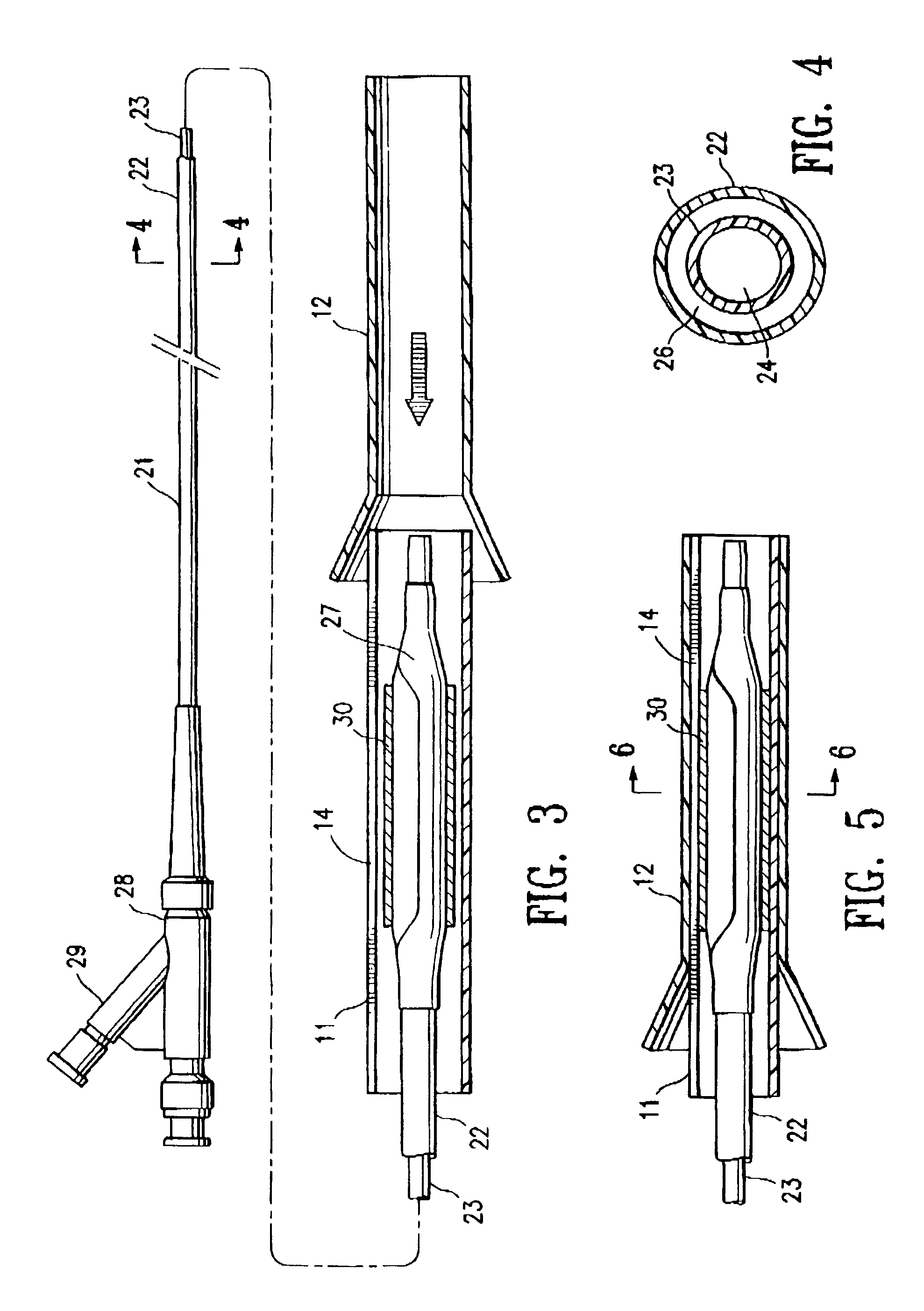
[0024]FIG. 1 illustrates a protector sleeve assembly 10 which embodies features of the invention, with an inner sleeve 11 and an outer sleeve 12. The inner sleeve 11 is illustrated in FIG. 1 in a relaxed configuration prior to being collapsed to a collapsed configuration by the force applied by the outer sleeve. The relaxed inner sleeve has a discontinuous cylindrical wall section 13 and a longitudinally extending cut-out region 14. The inner sleeve 11 has a length L1, which is preferably longer than the length L3 of the outer sleeve 12. The inner sleeve 11 is preferably formed of an injection molded polymeric tube formed of nylon, in which the cut-out region is formed during the molding process. The outer sleeve 12 has a tapered first section 16 and a nontapered second section 17. In the embodiment of FIG. 1, the tapered section 16 has an inner diameter ID3 and an outer diameter tapering toward the nontapered section 17. The nontapered section 17 has an inner diameter ID2 which is ...


PUM


Abstract

A protector sleeve assembly for a balloon catheter, configured for being removably disposed on at least a section of the catheter and preferably on at least the catheter non-inflated balloon prior to introduction of the catheter in a patient's lumen, including a radially collapsible inner sleeve, and an outer sleeve with a tapered section. The inner sleeve has a relaxed configuration with an inner diameter greater than the outer diameter of the noninflated balloon, and a collapsed configuration with an inner diameter less than the relaxed inner diameter. The outer sleeve is slidably positioned on at least a portion of the inner sleeve and has a tapered first section with an inner diameter tapering towards a nontapered second section, the nontapered second section having a substantially uniform inner diameter less than an outer diameter of the relaxed inner sleeve and configured to hold the inner sleeve in the collapsed configuration.

Description

BACKGROUND OF THE INVENTION[0001]This invention generally relates to catheters, and particularly protective sheaths for intravascular catheters for such as balloon catheters used in percutaneous transluminal coronary angioplasty (PTCA) or for the delivery of stents.[0002]In percutaneous transluminal coronary angioplasty (PTCA) procedures a guiding catheter is advanced in the patient's vasculature until the distal tip of the guiding catheter is seated in the ostium of a desired coronary artery. A guidewire is first advanced out of the distal end of the guiding catheter into the patient's coronary artery until the distal end of the guidewire crosses a lesion to be dilated. A dilatation catheter, having an inflatable balloon on the distal portion thereof, is advanced into the patient's coronary anatomy over the previously introduced guidewire until the balloon of the dilatation catheter is properly positioned across the lesion. Once properly positioned, the dilatation balloon is inflat...

Claims


Application Information

Patent Timeline
IPC IPC(8): A61F2/06A61M25/00A61M25/10
CPCA61M25/00A61M25/10A61M2025/1081
Inventor DURCAN, JONATHAN P.
Owner ABBOTT CARDIOVASCULAR
Learn More