Terahertz imaging for near field objects

a near field object and terahertz technology, applied in the field of terahertz or tray imaging systems, can solve the problems of inconvenient application, inconvenient acquisition of data, and inability to achieve coherent or incoherent thz radiation,

Active Publication Date: 2006-09-12
NEW JERSEY INSTITUTE OF TECHNOLOGY
View PDF7 Cites 15 Cited by
  • Summary
  • Abstract
  • Description
  • Claims
  • Application Information

AI Technical Summary

Benefits of technology

[0013]Near field imaging using a THz imaging system is realized in accordance with the principles of the present invention by utilizing an interferometric imaging detector array that includes detector elements disposed on a surface curved to match substantially the curvature of the wave front for received THz signals. Generally, the near field is an environment wherein the distance to an object of interest is on the order of 10–100 times larger than the physical size of the THz imaging array. Typical distances from the object or target to the imaging array is anticipated to be in the 0.5 m–50 m range. Curvature of the detector array corrects a distortion problem in prior THz imaging systems that utilized planar interferometric imaging arrays based on a planar wave front assumption for received THz signals.
[0016]In yet another embodiment of the invention, the THz imaging detector includes an interferometric detector array having a plurality of detector elements disposed over a detector surface, a range detector, and a controller. The range detector acquires the range or distance from the detector to the object of interest or target and supplies that information to the controller. In turn, the controller responds to the range information by controllably delaying each signal output from each detector element by a predetermined amount so that, when observed at a particular time instant, the detector element output signals represent signals detected from substantially the same wave front of the received THz signal from the target. In other words, the introduction of delay effectively adjusts the radius of curvature of the surface on which the detector elements reside so that the surface curvature is substantially matched to the curvature of the received THz signal wave front.
[0018]Additionally, the detectors can be disposed logarithmically along two orthogonal axes of the detector surface, whether planar or non-planar. In this latter embodiment, the detector surface is rotated by a predetermined amount about an axis normal to the two orthogonal axes and through their intersection. At each interval of rotation and until a full rotation (360°) is completed, THz signals are received from the target location and combined to form an image of the target. In this way, a detector array having relatively few detector elements can produce an imaging result comparable to an array having considerably more detector elements.

Problems solved by technology

These systems consequently take a significant amount of time to acquire sufficient data and thereby generate the image of even a single small object.
As a result, they are not suitable for applications that depend on real-time acquisition of THz images.
One difficulty with extending either of these techniques to continuous wave THz imaging of coherent or incoherent THz radiation is that coherent continuous wave or short-pulsed laser sources are required.
But imaging of an incoherent THz source is not possible through the use of any of these methods.
Therefore, the system described above would suffer inaccuracy in the detection and imaging of objects in the near field.
Techniques have not been proposed to date to deal with the problem presented by curved wave fronts experienced when trying to apply the far-field THz imaging systems to the near-field imaging application.

Method used


Image

  • Terahertz imaging for near field objects
  • Terahertz imaging for near field objects
  • Terahertz imaging for near field objects

Examples


Embodiment Construction

Overview of Imaging System

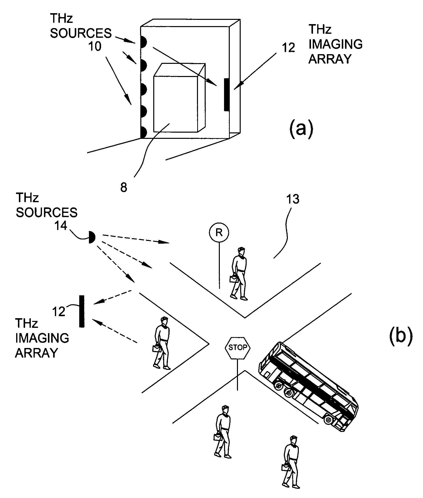
[0031]Terahertz (THz) imaging systems generally include two major components, namely, a THz transmitter or source and a THz receiver including an imaging array. These two components can be disposed either as shown in FIG. 1a for THz signal transmission through a target 8 or as shown in FIG. 1b for THz signal reflection by a target 13. The THz transmitter generates electromagnetic radiation at a desired THz frequency suitable for the imaging process and directs the radiation at the object or region of interest, which is also known as the target. The THz receiver includes both an imaging array comprised of a plurality of detector elements disposed on a surface to receive the THz signals from the target, via transmission or reflection, and a signal processor that converts the received THz signals into an image of the target from which the presence of specified compositions can be determined. This image is typically a frequency domain signature of the target th...


PUM

PropertyMeasurementUnit
field of viewaaaaaaaaaa
wavelengthsaaaaaaaaaa
distancesaaaaaaaaaa

Abstract

Near field imaging using a THz imaging system is realized by utilizing an interferometric imaging detector array that includes detector elements disposed on a surface curved, physically or artificially, to match substantially the curvature of the wave front for received THz signals. Generally, the near field is an environment wherein the distance to an object of interest is on the order of 10–100 times larger than the physical size of the THz imaging array. Typical distances from the object or target to the imaging array is anticipated to be in the 0.5 m–50 m range. Curvature of the detector array corrects a distortion problem in prior THz imaging systems that utilized planar interferometric imaging arrays based on a planar wave front assumption for received THz signals.

Description

CROSS-REFERENCE TO RELATED APPLICATION[0001]This application claims the benefit of priority from both U.S. Provisional Patent Application Ser. No. 60 / 537,076 filed on Jan. 16, 2004 and U.S. Provisional Patent Application Ser. No. 60 / 560,664 filed on Apr. 8, 2004. Each of the above applications is incorporated by reference herein in its entirety.GOVERNMENT RIGHTS[0002]The United States government may have certain rights in this invention. A portion of the work described herein was supported by the U.S. Army through an STTR Contract DAAD19-02-C-0085 and an SBIR Contract DAAD19-03-C-0137. Also, a portion of the work described herein was supported by the United States Technical Support Working Group (TSWG-ED) under Grant N41756-04-C-4163.BACKGROUND OF THE INVENTION[0003]1. Field of the Invention[0004]This invention relates to imaging apparatus and methods and, more particularly, to Terahertz or T-ray imaging systems and methods which utilize electromagnetic radiation in the Terahertz (T...

Claims


Application Information

Patent Timeline
Patent Type & Authority Patents(United States)
IPC IPC(8): G01J5/02G01J3/42G01N21/35G01S7/481G01S17/89H01L31/00
CPCG01J3/42G01N21/3581G01S13/89G01S17/89G01S7/4816G01N21/3563
Inventor FEDERICI, JOHN F.GARY, DALE E.
Owner NEW JERSEY INSTITUTE OF TECHNOLOGY
Why Eureka
Try Eureka