Distributed floating series active impedances for power transmission systems

a technology of active impedances and power transmission systems, applied in the direction of electric variable regulation, process and machine control, instruments, etc., can solve the problems of large power systems such as those in the united states and canada, which are of great complexity and can be vulnerable to power disruption events, and existing passive transmission systems generally are not well-suited to controlling power flow, etc., to reduce congestion on existing lines, effectively transmit more power, and optimize transmission system efficiency

Active Publication Date: 2006-09-12
SOFT SWITCHING TECH
View PDF28 Cites 74 Cited by
  • Summary
  • Abstract
  • Description
  • Claims
  • Application Information

AI Technical Summary

Benefits of technology

[0010]The invention may be implemented to control loop flows, thereby reducing congestion on existing lines so that they can effectively transmit more power. Appropriate control of the modules can be used to guide current along a preferred path through the transmission grid. In addition to optimizing transmission system efficiency, the invention may be utilized to balance phase currents and to inject harmonic voltage to help block harmonic current flows.
[0011]The present invention can be utilized at substantially lower cost than conventional FACTS systems because of the elimination of the need for high voltage insulation and because of relatively simple installation and commissioning of the modules. The utilization of a large number of standardized modules allows the use of mass manufacturing techniques and lowered cost of production for individual modules. Very high reliability can be achieved since a large number of the active impedance modules (in the hundreds or more) may be utilized, so that the failure of one or a few modules will have minimal effect on the system as a whole, and can be compensated for by appropriate control of the remaining modules. Conversely, where “N” modules are in place, an additional “M” modules may be deployed to achieve a desired N+M reliability level. The use of the active modules in accordance with the invention allows an increase in the steady-state line capacity while allowing control of the power flow and control of fault currents. Because the modules can be easily installed without having to physically disrupt existing power lines, and can be effectively installed in an incremental manner, the deployment of the active modules can be carried out with little or no risk to the power transmission system, allowing trial and validation of the system at low cost and low risk. These features also allow the number of units deployed to be increased as the economics permit. Furthermore, the individual modules are portable and can be decoupled from a transmission line, and reinstalled at another more advantageous location, if desired.

Problems solved by technology

Large power systems such as those in the United States and Canada are of great complexity and can be vulnerable to power disruption events that propagate through the system.
Building new transmission lines is both costly and time consuming, with several years generally being required to complete the land acquisition, permitting, and construction processes.
Existing passive transmission systems generally are not well-suited to controlling power flow from a generating site to a particular customer.
The existing systems are also subject to “loop flow,” wherein electricity flows along its path of least impedance and not along a desired contract path, which results in transmission line congestion, wheeling losses, inability to fulfill electricity supply contracts, and increased transmission loading relief (TLR) requests.
Adding new generation to existing transmission networks can also cause loop flows and fault protection coordination problems, with resulting poor utilization of both generation and transmission assets.
Furthermore, AC power transmission systems are inherently subject to relatively high losses when transmitting power over very long distances—several hundred to 1,000 miles or more—which has led to the limited use of high voltage DC power transmission lines and proposals for the use of superconducting lines in the future.
However, such proposals for alternatives to AC transmission lines are of uncertain practicality and, if feasible at all, would require very large investments and would not be operational for several years.
AC transmission lines typically operate well below thermal limits because of limits imposed by reliability or stability considerations, so that existing lines could potentially carry significantly more power if non-thermal constraints could be reduced.
Although technically viable, FACTS systems have not been commercially feasible to date because of the high cost of such systems.
These high costs are due to several factors, including high power ratings (20 to 100 MVA), which require the use of high power GTO devices in custom designs, making the overall system expensive to design, build, commission and operate.
High voltage ratings (as high as 345 kV) require expensive insulation and isolation requirements, and fault protection coordination requirements create high component stress, again resulting in high system cost.
The proposed FACTS systems have generally involved a single installation, or at most a handful of installations, of relatively large size (similar to a substation) yielding a critical single point of failure, with resulting poor reliability and potential unavailability.
As a consequence, the FACTS approach has not been implemented in a widespread commercial manner.

Method used


Image

  • Distributed floating series active impedances for power transmission systems
  • Distributed floating series active impedances for power transmission systems
  • Distributed floating series active impedances for power transmission systems

Examples


Embodiment Construction

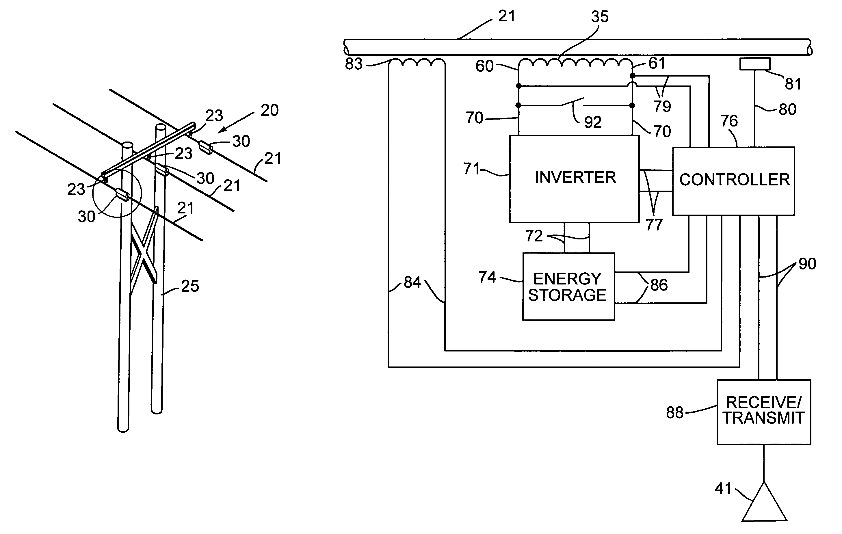
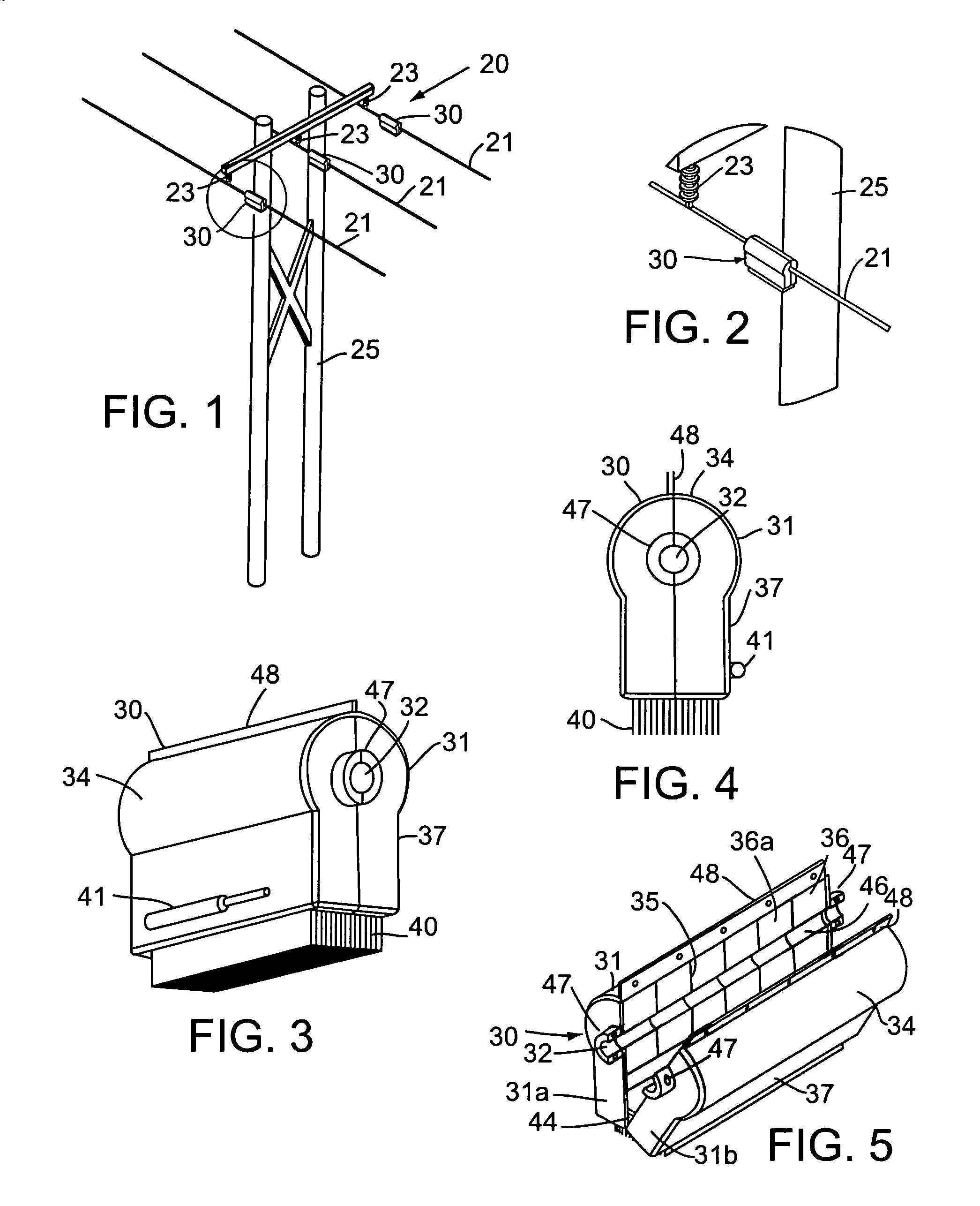
[0024]With reference to the drawings, FIG. 1 illustrates a set 20 of power transmission lines composed of three conducting lines 21 supported in a conventional manner by insulators 23 on support towers illustratively shown at 25. Individual transmission lines 21 carry current for each phase of a three-phase power transmission system in a conventional manner, and may operate at high voltages typical of long distance transmission systems, e.g., 138 kV to 750 kV. In accordance with the present invention, an active impedance module 30 is attached to each of the transmission lines 21 preferably, but not necessarily, near to the insulators 23 which support the power lines 21. As discussed further below, the active modules 30 are formed to attach to a power transmission line without requiring any physical modification or break in the power line. As illustrated in FIGS. 1 and 2, the impedance modules 30 preferably are solely supported by the power lines 21 and are neither physically connect...


PUM

PropertyMeasurementUnit
voltageaaaaaaaaaa
voltagesaaaaaaaaaa
impedanceaaaaaaaaaa

Abstract

Floating electrically isolated active impedance modules are formed to attach to power transmission lines without breaking the lines such that the power line forms a secondary of the main transformer of the module. Each module includes an electrical energy storage device and a switching circuit, such as a single phase inverter, connected to the storage device and to the main transformer primary winding. The inverter can be controlled to couple a selected voltage to the transmission line through the main transformer primary winding which can provide effective positive impedance, negative impedance, or a voltage at or near phase quadrature with the line current. Many active impedance modules may be distributed over a power system grid to allow control of the impedance of the power lines in the grid and to steer power through the grid, with each module electrically isolated from ground and from other phase lines of the transmission system.

Description

FIELD OF THE INVENTION[0001]This invention pertains generally to the field of electrical power transmission systems and particularly to the control of power flow in power transmission systems.BACKGROUND OF THE INVENTION[0002]Electrical power distribution systems are formed of a complex interconnected system of generating plants, substations, and transmission and distribution lines. Large power systems such as those in the United States and Canada are of great complexity and can be vulnerable to power disruption events that propagate through the system. To meet the increasing demand for electrical power and to reduce the vulnerability of the power systems to disturbances, it will be necessary to substantially increase transmission capacity. Building new transmission lines is both costly and time consuming, with several years generally being required to complete the land acquisition, permitting, and construction processes.[0003]Transmission and distribution lines normally are passive ...

Claims


Application Information

Patent Timeline
Patent Type & Authority Patents(United States)
IPC IPC(8): G05F1/66G05F1/70G05F1/00H01F30/16H01F38/14H02J1/10H02J3/18H02M
CPCH01F30/16H02J3/1814H01F38/14Y02E40/18Y02E40/10
Inventor DIVAN, DEEPAKRAJ M.SCHNEIDER, ROBERTBRUMSICKLE, WILLIAM E.
Owner SOFT SWITCHING TECH
Why Eureka
Try Eureka