
Keyless access sensor system

Inactive Publication Date: 2006-09-12
HONEYWELL CONTROL SYST
View PDF7 Cites 21 Cited by
  • Summary
  • Abstract
  • Description
  • Claims
  • Application Information

AI Technical Summary

Benefits of technology

[0009]The sensor device for keyless access generates a primary beam of electromagnetic radiation, particularly in the optical wavelength range and, more particularly, it is a pulsed beam, this beam being located near a door handle. In the case of a vehicle, the beam is located between the door panel and the inside of the handle. Alternatively, the beam is located between the two extremities of the handle and parallel to the door panel in order to detect and anticipate any action of opening the door made by the user. When a user inserts his hand to fully or partially interrupt or reflect the beam after the system is primed, the system detects this modification of the beam characteristics and generates the output signal which is used in anticipation with the user ID to create a control signal to unlock or open the door before any action on the door handle. The sensor device for keyless access may include a backup switch which will provide a signal to the general processor in case the modification of the primary beam characteristics due to the presence of the hand is not detected by the sensor system for whatever reason. This backup switch will be activated by the mechanical action of the user on the door handle in order to open the door. The signal issued from the backup switch will then initiate the user ID sequence and will then allow the unlocking of the door with a delay due to the lack of anticipation in the detection of the action of opening the door by the user. The backup switch may be a mechanical switch or an optical switch or the like. The sensor device for keyless access device may also include a locking switch, which purpose is to cause locking of the door when this locking switch is actuated by the user when he exits the door. In the case of a vehicle the locking switch is locatable on the handle for easy actuation by the user.
[0016]Another particular advantage of this arrangement for the use by vehicles is that it will still be fully functional even in harsh environments due to bright artificial lights in towns by night, or high temperature or presence of dust on the car, or the like. This functionality is provided by the optical adaptive feedback system and the ambient light protection function of the sensor device.

Problems solved by technology

One problem with the existing key and lock arrangements is that loss or damage to the key can render access impossible.
One other problem is that the use of a key requires a specific action such as unlocking a door latch with the key from the authorized person before an action of opening the door associated with the door latch.
This specific action is very often not easy to accomplish, is not ergonomic and is time-consuming.
One problem with this arrangement is that the user still has to initiate a specific action such as, in the case of a fob, taking the fob in his hand and pressing on the fob button, or in the case of a magnetic card or the like, inserting the card in a slot or to present it in front of a card reader / detector or the like, in order to unlock the door and have access to the vehicle, these specific actions being time-consuming and not ergonomic.
One other problem with this arrangement is that if the user decides not to enter the vehicle but forgets to actuate the “lock” signal, the car and / or building remains open and is thus vulnerable.
In addition, with existing keyless locking systems, particularly for vehicles, a conventional locking mechanism is used which is susceptible to interference by thieves to gain access to the car.
For buildings, conventional locks are actuated in the same way and are susceptible to the same procedures by intruders to gain access to the premises.

Method used


Image

  • Keyless access sensor system
  • Keyless access sensor system
  • Keyless access sensor system

Examples


Embodiment Construction

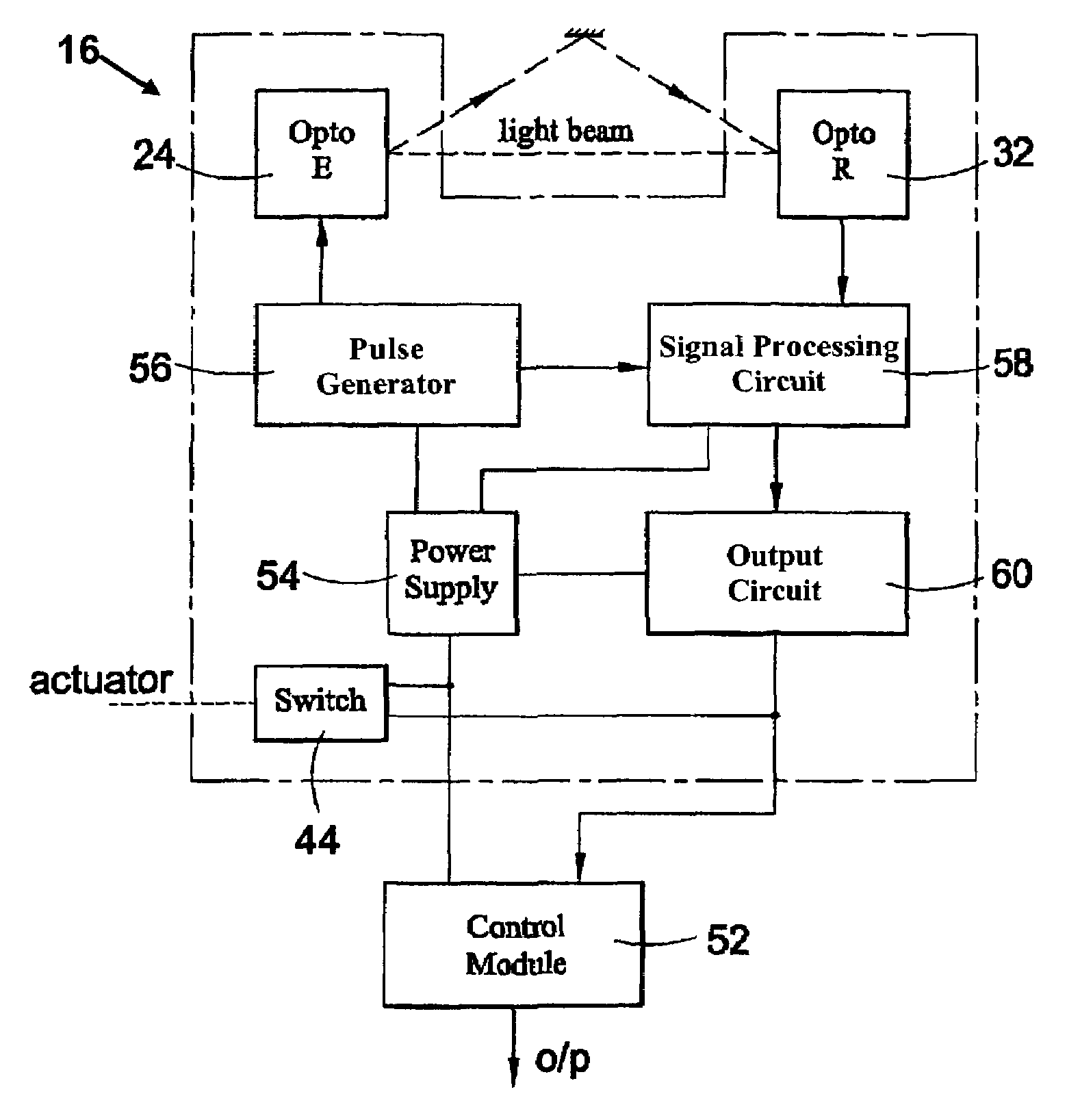
[0027]According to one aspect of the present invention, there is provided a sensor system for use with a keyless access control system, the sensor system comprising:

[0028]an electromagnetic radiation generating element for generating an incident beam of electromagnetic radiation in the form of a pulse train;

[0029]an electromagnetic sensing element for sensing the incident beam, and

[0030]a signal processor coupled to the sensing element for detecting an interruption to, or modification of, the incident beam, the signal processor including a timer for detecting when the duration of the interruption or modification of the incident beam is greater than a predetermined by detecting the presence of absence of a predetermined number of pulses varying from a predetermined level, the signal processor for providing an output signal to an access control mechanism when the presence of absence of a predetermined number of pulses are counted.

[0031]Preferably, the system includes a backup switch f...


PUM


Abstract

A keyless access sensor system for use with a keyless access control mechanism (KACM) is described for controlling the operation of a locking device. The KACM receives a signal from a sensor device for keyless access to create a first output signal before the user has begun any action on the handle in order to open the door. The first output signal is sent to a general processor, which initiates a recognition process and, after recognition of the authorized user the processor then generates an unlocking signal which unlocks the locking device before the authorized user will have fully accomplished the action of opening the door. Thus the authorized user is allowed to open the door without any specific un-ergonomic and time-consuming additional action to the simple action of actuating the handle to open the door. The second signal is generated by a device, such as a fob, card or the like, carrying a unique digital or analog identification in response to RF or IR interrogation from the general processor after it receives the output signal from the sensor device for keyless access.

Description

CROSS-REFERENCE TO RELATED APPLICATIONS[0001]This application is a continuation of International application PCT / GB01 / 02919, entitled “Keyless Access Sensor System” filed Jun. 29, 2001 and published as International Publication No. WO 02 / 02893 A1, the entire content of which is expressly incorporated herein by reference thereto.BACKGROUND[0002]The present invention relates to a keyless access sensor system and its associated sensor device for keyless access particularly, but not exclusively, for use in allowing access by an authorized user to a vehicle, building or the like. The invention also relates to a method of using a keyless access sensor system to control entry of authorized persons and to a circuit for processing signals in a keyless access sensor system.[0003]It is important, for many reasons, to control access to premises, vehicles and personal property so that only authorized users are allowed access. Typically this is done using keys which fit a lock to allow the user o...

Claims


Application Information

Patent Timeline
IPC IPC(8): G08B29/00E05B49/00B60R25/01B60R25/24B60R25/31E05B81/54G07C9/00
CPCE05B81/78G07C2209/64G07C2009/00785E05B85/16E05B49/00
Inventor NEVEUX, ANTOINEGIERCZAK, MAREKSCHWEIZER, PASCALSHELLEY, MICHAEL JAMES
Owner HONEYWELL CONTROL SYST
Features
  • Generate Ideas
  • Intellectual Property
  • Life Sciences
  • Materials
  • Tech Scout
  • Unparalleled Data Quality
  • Higher Quality Content
  • 60% Fewer Hallucinations
Learn More