Eureka AIR delivers breakthrough ideas for toughest innovation challenges, trusted by R&D personnel around the world.

Reducing distortion of signals

Inactive Publication Date: 2006-09-12
ANDREW LLC
View PDF19 Cites 80 Cited by
  • Summary
  • Abstract
  • Description
  • Claims
  • Application Information

AI Technical Summary

Benefits of technology

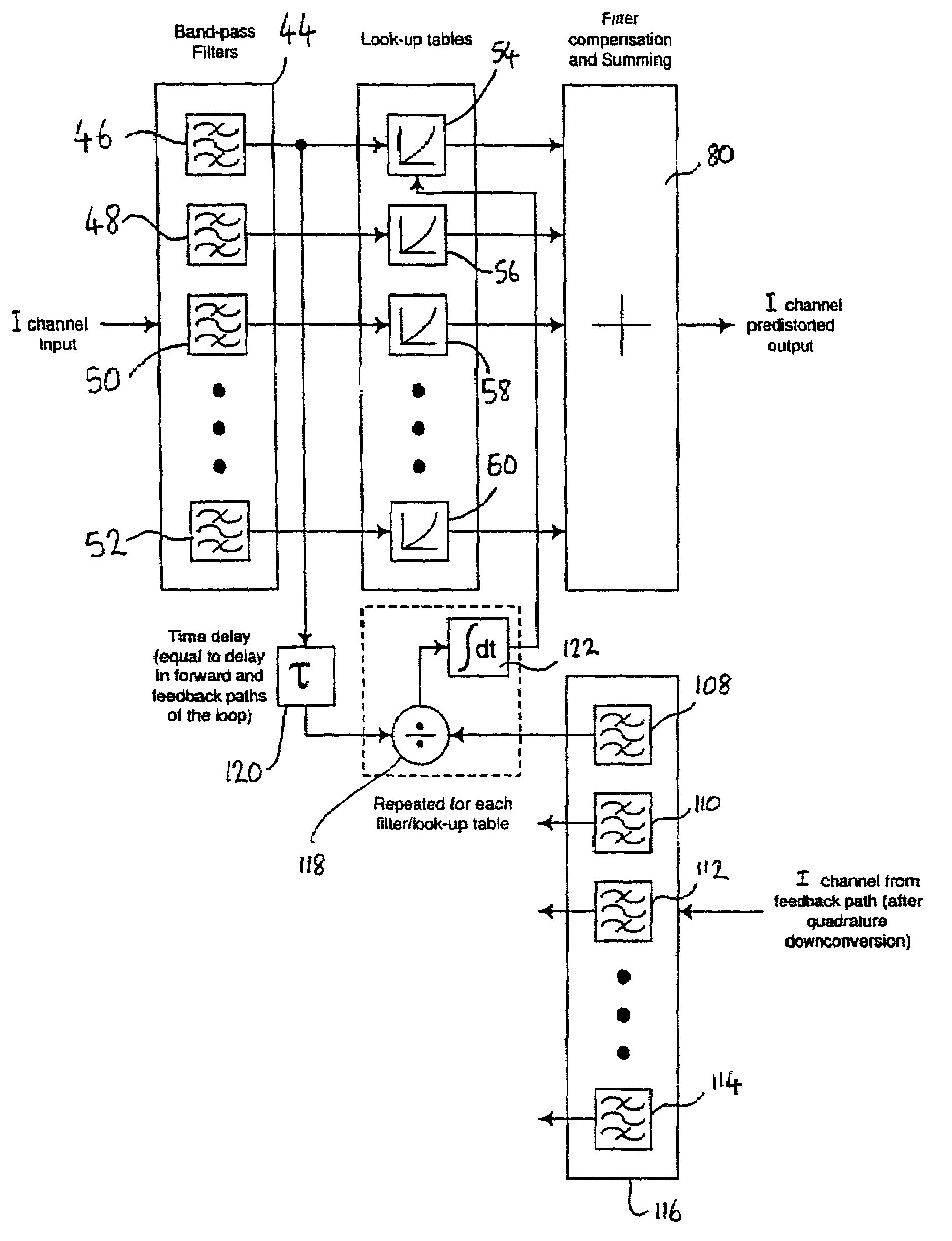
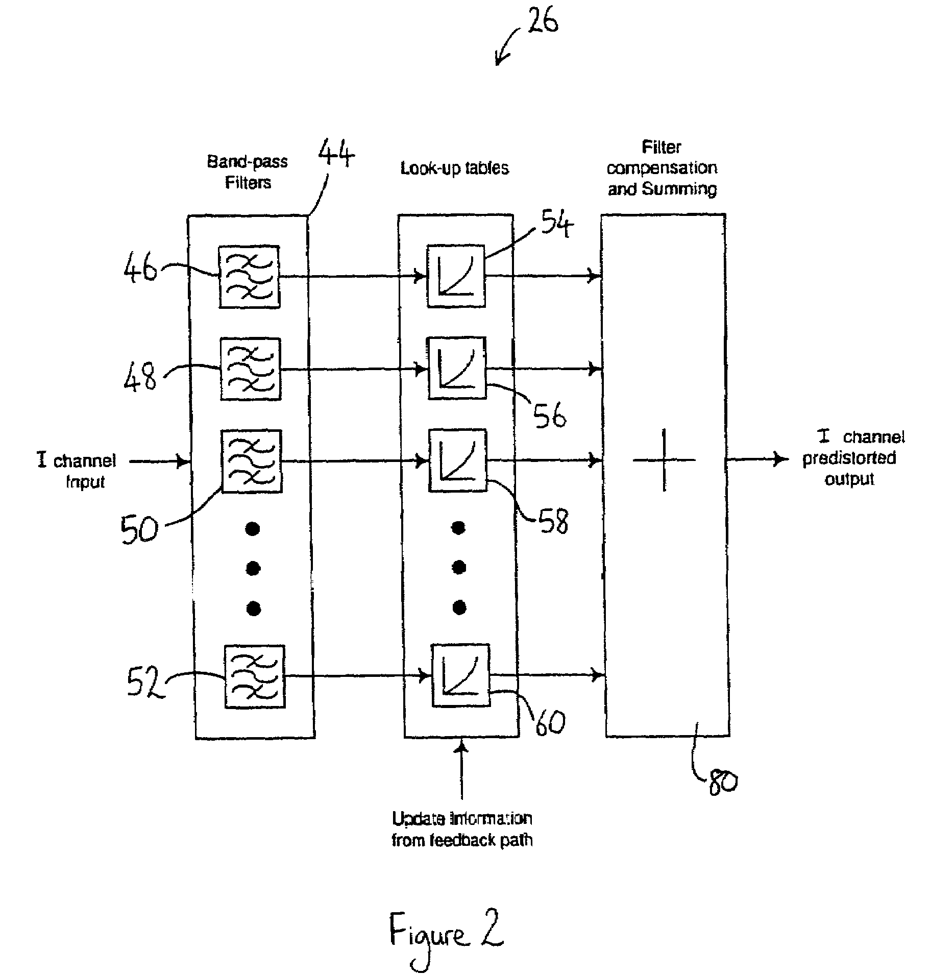
[0006]According to one aspect, the invention provides a lineariser for reducing distortion of an output signal of signal handling means by processing a raw signal with data selected from storage means in response to the amplitude and frequency content of the raw signal. A lineariser of this type is versatile in that it can linearise, i.e. reduce distortion of, a signal which has experienced a distortion which varies with both amplitude and frequency. In addition, it is possible to adapt the data in the storage means so that the distortion reduction processing can be adapted to changes in the distortion.
[0011]Another advantage of the lineariser is that the data in the storage means may be altered to adapt distortion reduction processing to changes in the distortion. Preferably, therefore, the lineariser comprises means for adapting the data in the storage means to compensate for changes in the distortion characteristics of the signal handling means. Advantageously, the adapting means comprises means for monitoring feedback from the output of the signal handling means.
[0014]The above method may be used to reduce distortion of an output signal of signal handling means in a transmitter, so that the output of the transmitter is linearised.

Problems solved by technology

The use of conventional single channel linearisation schemes (e.g. Cartesian loop) suffer in that they are capable of controlling linearisation only over a finite gain-bandwidth.
Such systems are not capable of providing the required linearity improvements (“gain”) over the channel bandwidths envisaged (for UMTS, in particular).
Alternative broadband linearisation schemes, such as feed-forward arrangements, are difficult to implement as integrated circuits.
They are also unable to attain desired levels of power efficiency because they employ additional linear amplifiers to perform distortion cancellation.

Method used


Image

  • Reducing distortion of signals
  • Reducing distortion of signals
  • Reducing distortion of signals

Examples


Embodiment Construction

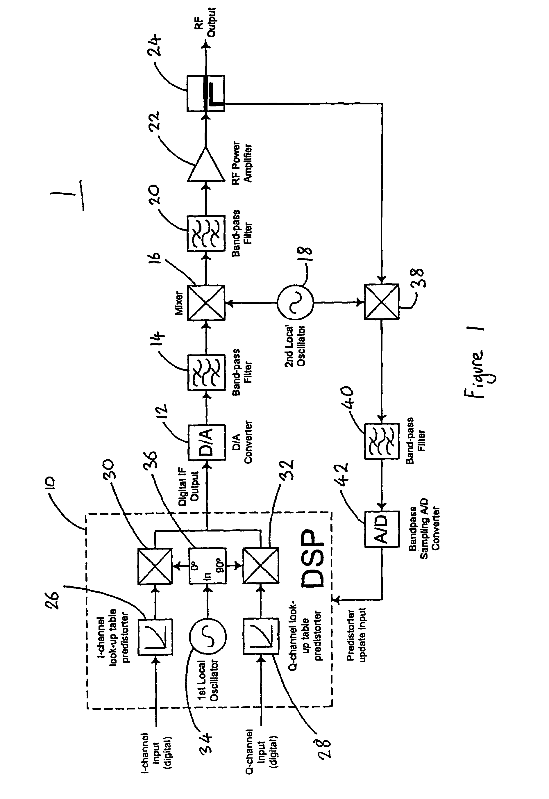
[0023]With regard to FIG. 1, the transmitter, generally indicated 1, produces a radio frequency (RF) output from a baseband, digital input signal in quadtrature format. The quadrature input signal comprises an inphase channel input I and a quadrature channel input Q (phase displaced by 90° with respect to the I channel).

[0024]The transmitter 1 comprises a digital signal processor (DSP) 10 which receives the I and Q channels as inputs. The digital signal processor 10 predistorts the input signal (i.e. its I and Q components) and performs frequency up conversion of the predistorted input signal from the baseband to the intermediate frequency (IF) band. The DSP 10 supplies this digital IF band predistorted signal to a digital to analogue converter (DAC) 12 which supplies an analogue version of this signal to band pass filter 14. Mixer 16 combines the output of filter 14 with a signal from local oscillator 18 and produces an output spectrum which contains signals in a RF band destined f...


PUM


Abstract

A predistorter (26) comprises an array (44) of band pass filters (46 to 52) which divide an input signal into components. Each of the components is manipulated using coefficients retrieved from respective look-up tables (54 to 60). The amplitude of each component is used to retrieve a coefficient from its respective look-up table. The amplitude of each component is then multiplied with its respective retrieved coefficient to generate a predistorted amplitude for that component. The predistorted amplitudes are summed (at 80) to produce a predistorted input signal. The predistortion of the input signal is arranged to counter the distortion characteristic of a signal handling element (such as non-linear power amplifier 22 in FIG. 1) to which the predistorted input signal is subsequently supplied. The coefficients in the look-up tables (54 to 60) can be adapted using feed back from the output of the signal handling means (FIG. 5). Fast Fourier transformation and inverse fast Fourier transformation can be used in place of band pass filter array (44) and combiner (80), respectively (FIG. 4).

Description

FIELD OF THE INVENTION[0001]This invention relates to a lineariser for reducing distortion of an output signal of signal handling means.BACKGROUND OF THE INVENTION[0002]The GSM-EDGE and UMTS standards place an increasingly stringent requirement on the linearity of handset transceiver circuits, particularly given the proposed wide channel band widths of handset transceivers compared to, for example, DAMPS and PDC systems. In order to realise a power efficient handset design, some form of linearisation will be required in the handset transceiver. This should be low power itself, capable of broadband linearisation (up to 5 MHz for UMTS / UTRA), frequency flexible, preferably multiband, and capable of achieving and maintaining high levels of linearity improvement when used to reduce distortion caused by highly non-linear power amplifiers (e.g. class-C amplifiers).[0003]The use of conventional single channel linearisation schemes (e.g. Cartesian loop) suffer in that they are capable of con...

Claims


Application Information

Patent Timeline
IPC IPC(8): H04K1/02H04L25/03H04L25/49H03F1/32
CPCH03F1/3258H03F1/3252
Inventor KENINGTON, PETER
Owner ANDREW LLC
Why Eureka
Eureka Blog
Learn More