Multiple bone tracking

a multi-bone, tracking technology, applied in the field of multi-bone tracking, can solve the problems of significant patient trauma, post-operative pain, and potential error, and achieve the effect of accurate tracking

Active Publication Date: 2006-09-12
ORTHOSOFT ULC
View PDF14 Cites 140 Cited by
  • Summary
  • Abstract
  • Description
  • Claims
  • Application Information

AI Technical Summary

Benefits of technology

[0010]Accordingly, an object of the present invention is to provide a method for, and an apparatus permitting, the accurate tracking of a multi-bone moveable structure using a single reference tracker adapted for communication with an image guided surgical system.
[0012]It is another object of the present invention to provide a vertebral clamp capable of providing variably selective compression and extension of vertebral bodies engaged therewith.
[0013]It is another object of the present invention to provide a surgical tool capable of simplifying, improving the precision, or improving speed of spinal implant surgery.
[0014]It is another object of the present invention to provide a CAS multi-vertebral reference clamp capable of simplifying the use of fluoroscopy for surgical navigation.
[0017]In accordance with the present invention, there is additionally provided a method for monitoring position and movement of vertebrae using an image guided surgical system, comprising the steps of: attaching a rigidly connected multiple-point anchor assembly to at least two vertebrae located within a frame of reference of the image guided surgical system, thereby immobilizing the vertebrae relative to one another, the multiple-point anchor assembly being trackable and adapted to be located in three dimensional space by the image guided surgical system; and performing a registration of the at least two immobilized vertebrae, the immobilized vertebrae being tracked together permitting at least one of facilitated and improved registration.

Problems solved by technology

The use of screws, installed into the pedicle region of each vertebra requiring immobilization, remains a critical mainstay of spinal corrective surgery, but one fraught with a potential for error that, even given today's surgical devices and procedures, remains significant.
Traditional spinal surgical operations are highly invasive, often requiring large incisions which, while necessary to achieve sufficient spinal exposure, result in significant patient trauma and post operative pain.
However, surgical navigation in the spine, where multiple vertebral bodies can move relative to each other, as a result of patient breathing or other body movement for example, creates navigation difficulties unique to spinal surgery in general, and to pedicle screw placement and insertion in particular.
While only limited displacement between vertebrae naturally occurs, even the slightest movement of the patient during surgery, for example movement resulting from breathing, can cause enough relative displacement of the other vertebrae with respect to the one being tracked to cause their inaccurate depiction.
Therefore the precise position and movement of the entire section of interest of the spine cannot be accurately located with only a single vertebra being tracked.
Using individual tracking elements for each rigid body in spine surgery, while permitting intra-operative detection of each anatomical element, is impractical as having detectable members fixed to each vertebra takes up considerable space within the surgical field, limiting the workspace available to the surgeon, and often additionally resulting in a higher level of invasiveness.
However, if each rigid body is not individually detectable, any movement of the anatomical structures relative to one another during surgery can cause the pre-operatively scanned images to misrepresent the intra-operative anatomy, a possibility that could eventuate in very grave consequences.
Additionally, when the spinal column in particular is the multiple-bone anatomical structure of interest, there exists difficulty in tracking all of its constituents.
While spinal column bone clamps adapted to be fastened onto vertebra are known, whether tracked or not, it generally remains difficult to track the sacrum with these standard vertebral clamps currently in use.
As the sacrum generally has very little process portion which protrudes, the sacrum provides no convenient clamping point permitting simple engagement of a tracked bone reference clamp.
Without using a bone reference which requires fastening to the sacrum body using bone screws for example, it is currently difficult to use standard vertebrae reference clamps in order to identify and track the sacrum with an image guided surgery system.

Method used


Image

  • Multiple bone tracking
  • Multiple bone tracking
  • Multiple bone tracking

Examples


Embodiment Construction

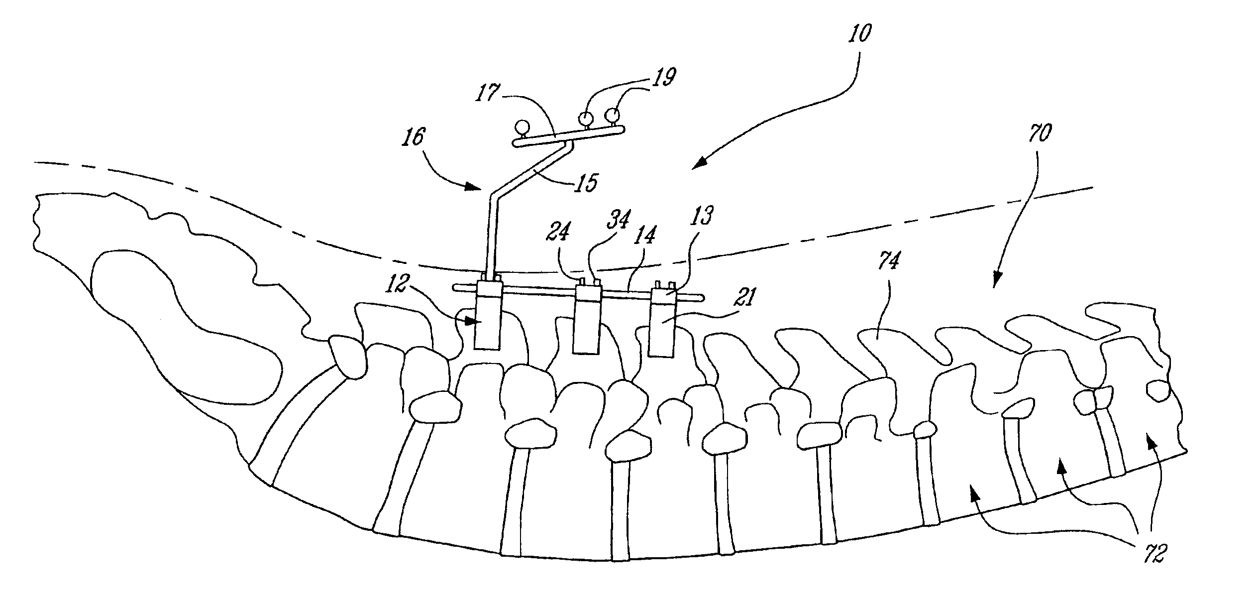
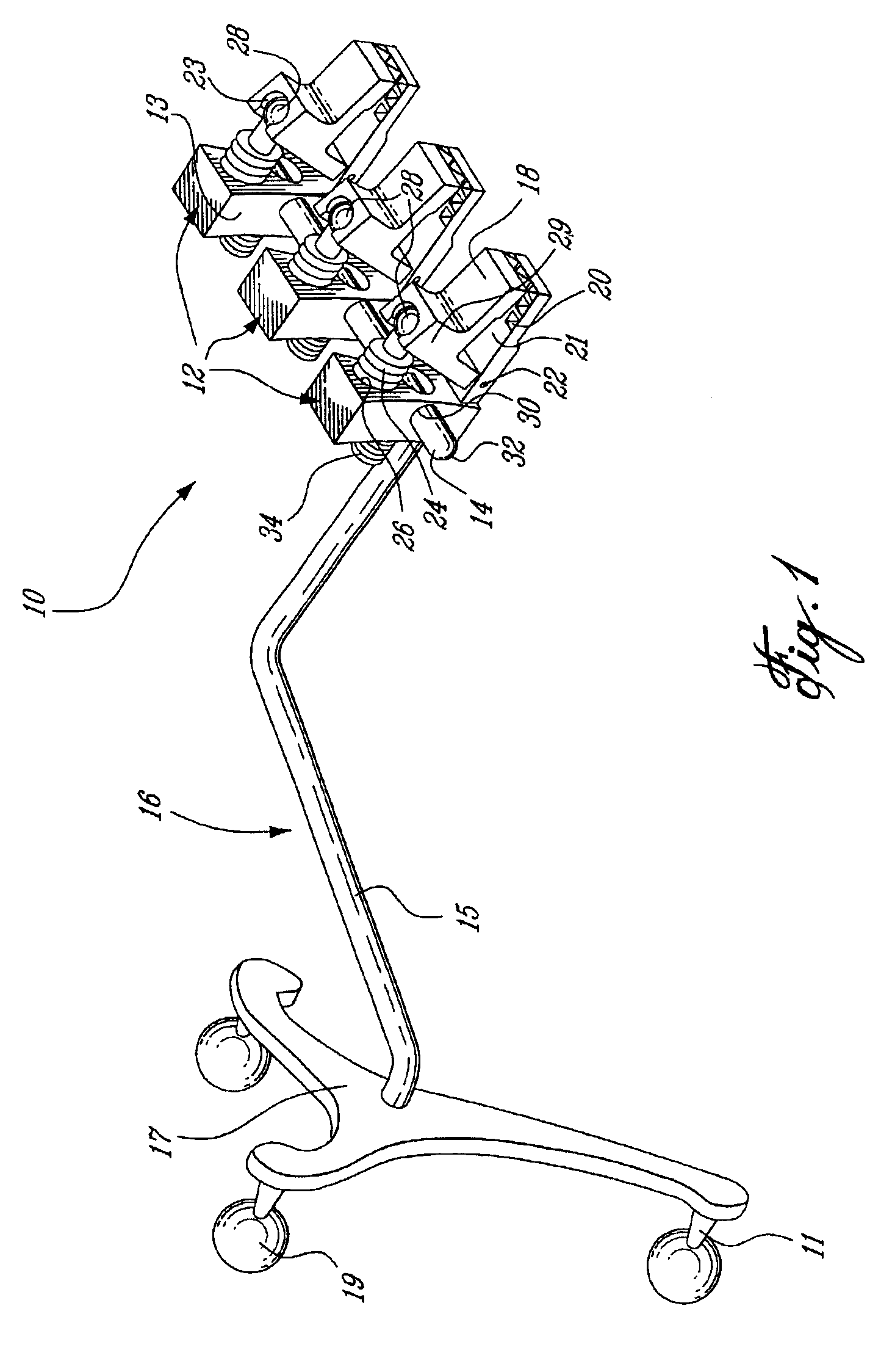
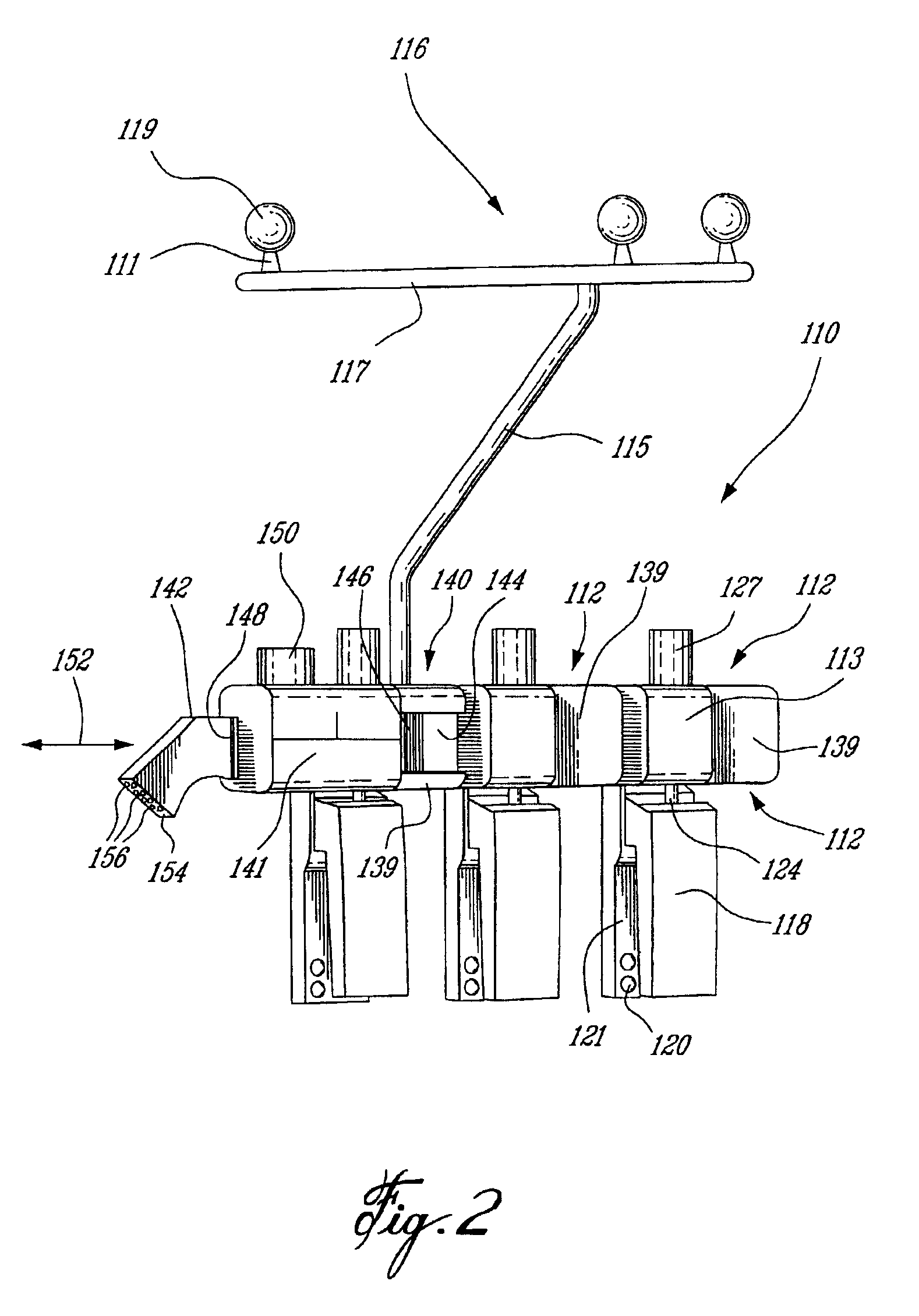
[0025]Referring to FIG. 1, a surgical bone reference multiple-clamp assembly 10 preferably adapted for use with a CAS system capable of tracking the device. The multiple-clamp assembly 10 generally comprises at least two anchoring members 12 adapted for removably fixation to bones of the patient. The multiple-clamp assembly is preferably for use with vertebrae of the spinal column, such that several vertebrae can be clamped together, restraining all relative movement therebetween, and subsequently tracked as a single body. This permits accurate determination of the position and orientation of several normally articulated bone structures of a linkage without requiring a plurality of trackable members which would clutter the surgical field. When used as a reference clamp for vertebrae, the present multiple-clamp assembly preferably comprises three anchoring clamps 12, adjustably fastened together with a linking bar 14 to form a rigidly connected triple clamp. The trackable member 16 i...


PUM


Abstract

A surgical device adapted for use with an image guided surgical system to facilitate monitoring inter-dependently mobile bone elements. A rigidly connected multiple-point anchor assembly is releasably engageable to at least two inter-dependently mobile bone elements and immobilizes the bone elements such that no relative movement therebetween is possible, and a complex rigid body comprising the immobilized bone elements and the multiple-point anchor assembly is formed. A trackable member is fastened to the multiple-point anchor assembly and comprises a detectable element adapted to be located and tracked in three dimensional space by the image guided surgical system, thereby defining position and movement of the complex rigid body.

Description

FIELD OF THE INVENTION[0001]The present invention relates generally to an apparatus and method for multi-bone tracking, and more particularly to a trackable multi-vertebrae clamp for use with a computer assisted surgical system, and particularly for pedicle screw placement.BACKGROUND OF THE INVENTION[0002]Increasingly common spinal surgical procedures, such as those performed to treat deforming spinal conditions for example, often require immobilizing or fusing vertebrae together by installing surgical implants to the affected bone structures. The implantation of pedicle screw fixation systems to correct and stabilize congenital and acquired deformities, trauma and degenerative diseases of the spine is well known. Such implants often include, for example, various screws or hooks fixed to vertebrae and linked by rods, plates or wires. Many different vertebra mounted spinal implants are known, however most share a common requirement for fixation of an element to a vertebral body: scre...

Claims


Application Information

Patent Timeline
Patent Type & Authority Patents(United States)
IPC IPC(8): A61B5/05A61B19/00A61B6/00A61B17/56A61B17/17A61B17/88
CPCA61B19/5244A61B19/54A61B17/1757A61B2019/5483A61B2019/505A61B2019/5255A61B2090/3983A61B2034/2055A61B34/20A61B2034/105A61B90/39
Inventor JUTRAS, SEBASTIENPICARD, DOMINICCOUTURE, PIERREPOULIN, FRANCOISAMIOT, LOUIS-PHILIPPEANGLEHART, JAMES
Owner ORTHOSOFT ULC
Why Eureka
Try Eureka