Variable valve actuating mechanism for internal combustion engine

a technology of internal combustion engine and variable valve, which is applied in the direction of machines/engines, couplings, lubricating auxiliaries, etc., can solve the problems of undesired variation in torque produced by internal combustion engine, affecting idling performance, and small lift quantity, so as to reduce non-uniform temperature distribution

Active Publication Date: 2006-09-19
NISSAN MOTOR CO LTD
View PDF9 Cites 46 Cited by
  • Summary
  • Abstract
  • Description
  • Claims
  • Application Information

AI Technical Summary

Benefits of technology

[0008]It is, therefore, an object of the present invention to provide a lift and operating angle varying mechanism to reduce temperature nonuniformity in the longitudinal direction, of the control shaft arranged to rotate to vary valve lift and / or valve operation angle.
[0011]According to still another aspect of the invention, a variable valve actuating apparatus comprises: a lift and operating angle varying mechanism which includes a control shaft extending in a longitudinal direction from a first end to a second end along a cylinder row of the engine, and which is arranged to vary an intake valve operation angle and an intake valve lift of the engine continuously by rotating the control shaft; a plurality of bearings supporting rotatably the control shaft; and means for supplying a lubricating oil to the bearings so as to reduce nonuniformity in temperature distribution of the control shaft in the longitudinal direction. The lubricating supplying means may include at least one of means (such as one or more holes formed in the control shaft and an oil hole formed in at least one of the shaft bearings) for supplying the lubricating oil to the bearings through an inside hollow section formed in the control shaft; and means (such as external piping to spray or drop the lubricating oil onto the control shaft) for supplying the lubricating oil onto the outer surface of the control shaft.

Problems solved by technology

In this apparatus, however, the intake air quantity is controlled without resort to a throttle valve, and therefore, the valve lift quantity becomes very small in a very low load operation such as idling, so that the idling performance can be adversely affected from engine start to sufficient warm-up.
This temperature unevenness causes uneven thermal expansion in the longitudinal direction of the control shaft, and thereby causes variation in the intake valve lift quantity among the cylinders, resulting in undesired variation in torque produced by the internal combustion engine.

Method used


Image

  • Variable valve actuating mechanism for internal combustion engine
  • Variable valve actuating mechanism for internal combustion engine
  • Variable valve actuating mechanism for internal combustion engine

Examples


first embodiment

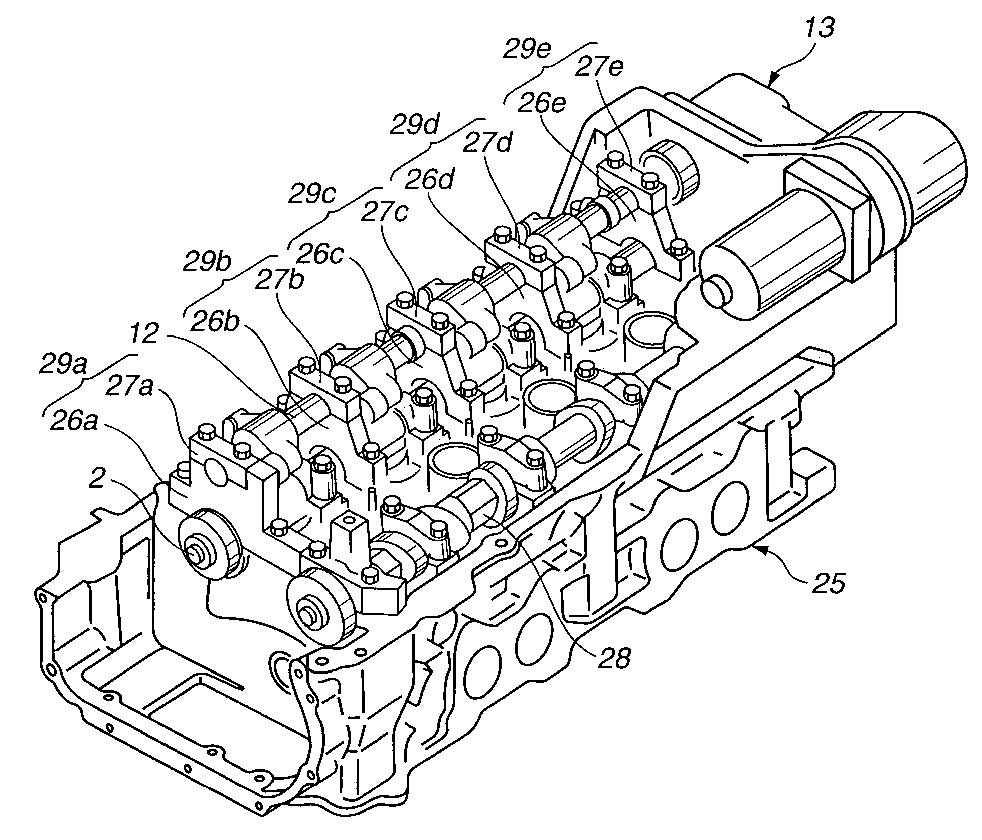
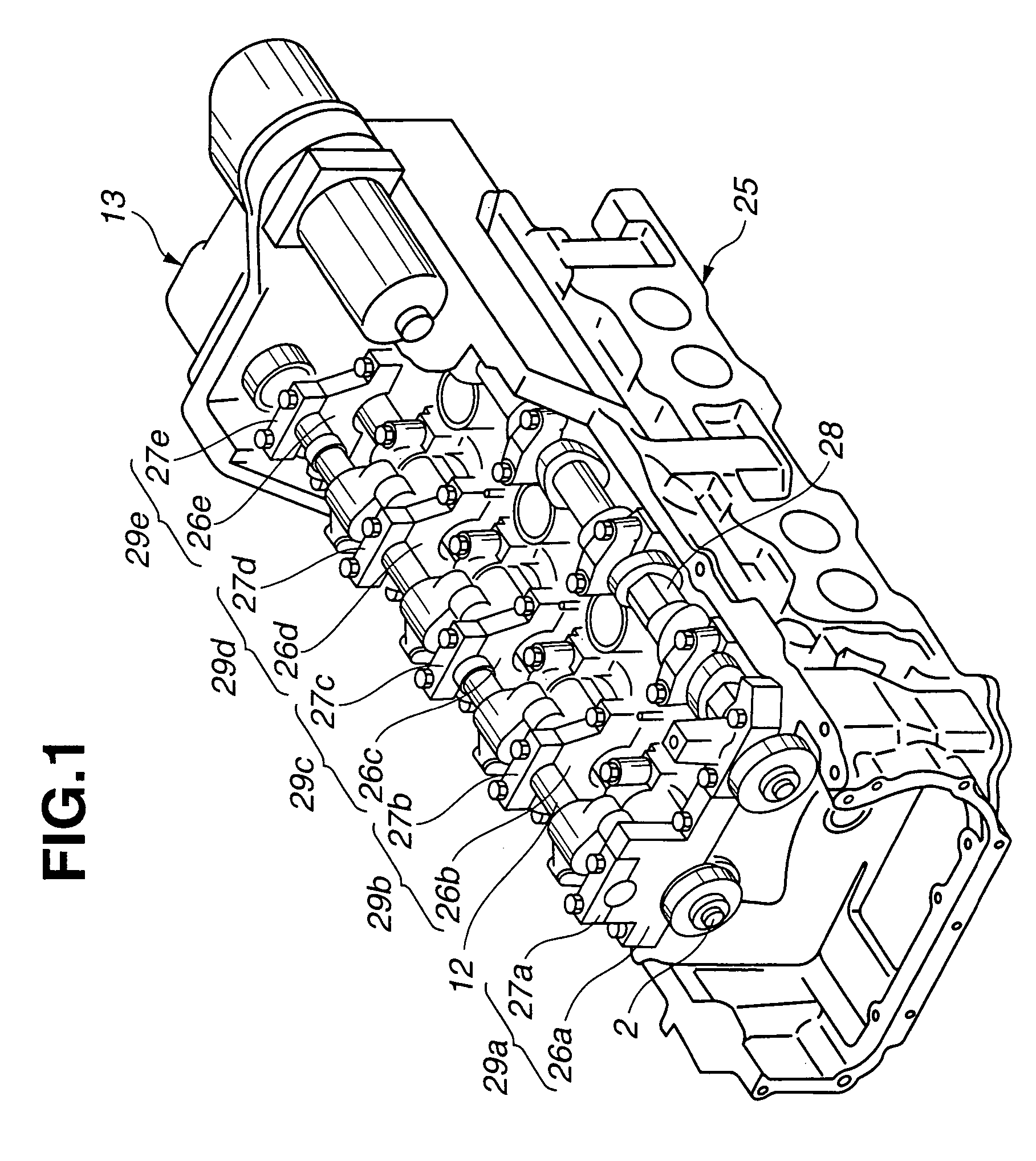
[0022]FIGS. 1–4 show a variable valve actuating system or apparatus according to the present invention. In this embodiment, the invention is applied to an inline four-cylinder engine. However, the present invention is also applicable to an internal combustion engine with other cylinder arrangement such as a V-type engine, and a six-cylinder or other multi-cylinder engine.

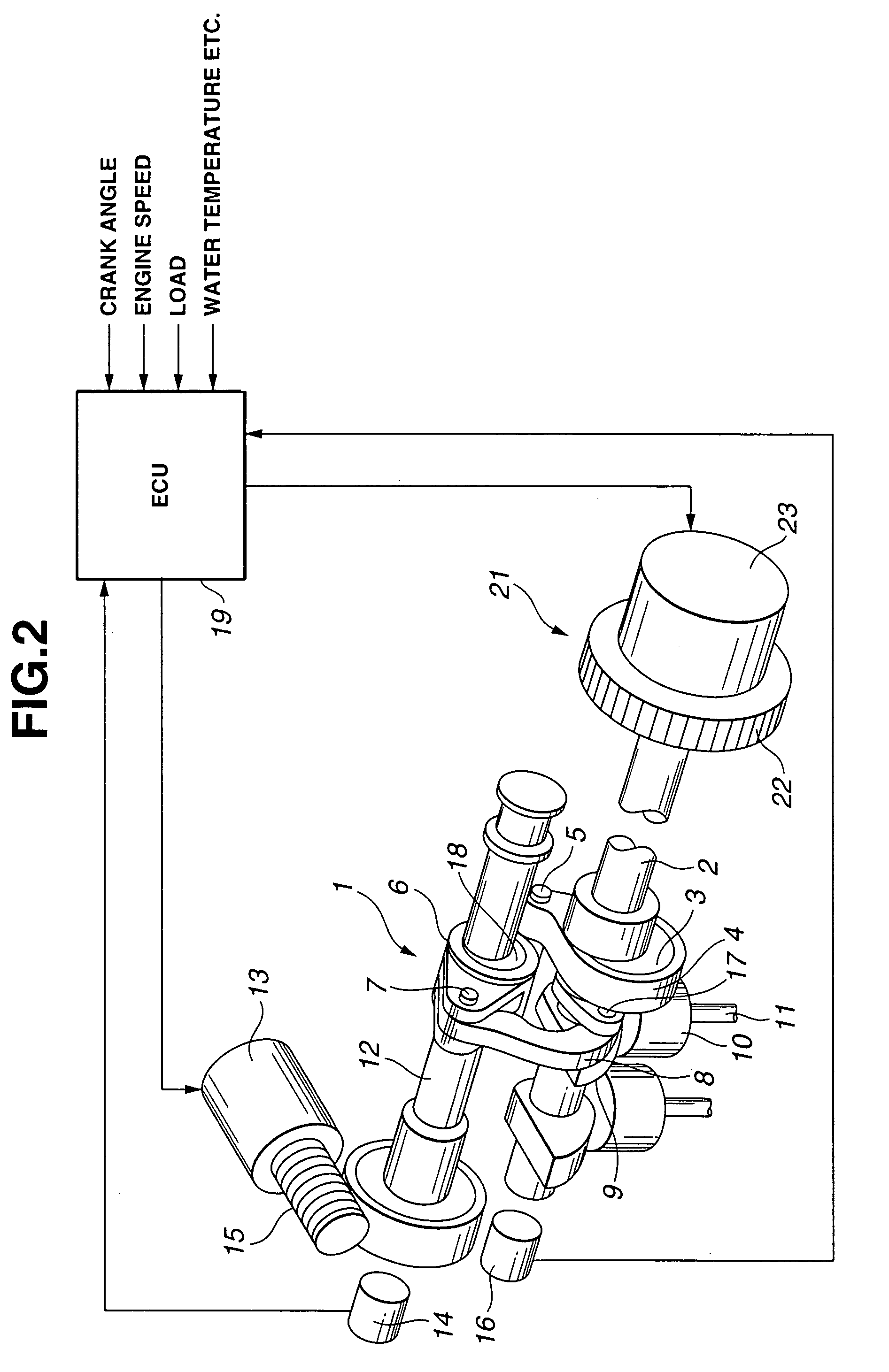
[0023]The variable valve actuating system, shown in FIGS. 1 and 2, for varying a valve lift characteristic of intake valves continuously includes, in combination, a lift and operation angle varying or control mechanism 1 capable of varying a intake valve lift quantity and an intake valve operation angle, and a phase varying or control mechanism 21 for advancing or retarding a center phase (phase with respect to crank angle (not shown)). In this example, an exhaust cam 28 is an ordinary direct drive type cam (with fixed lift and operation angle, and fixed lift center phase) to open and close an exhaust valve. However...

second embodiment

[0059]In the second embodiment, the temperature of lubricating oil from lubricating oil supply pipe system 40 is not influenced by actuator 13, the temperature of bearing 29e nearest to actuator 13 can be further increased relatively. Thereby, this arrangement can further reduce the temperature unevenness of control shaft 12 in the longitudinal direction, further reduce variations in intake valve lift quantity among cylinders, and reduce variation in torque of the internal combustion engine.

[0060]FIG. 9 shows one practical example according to a third embodiment of the present invention. In the third embodiment, lubricating oil supply pipe 40 is arranged to differentiate the amounts of the lubricating oil supplied to five bearings 29 in accordance with the location of the bearing 29 through which the lubricating oil is supplied into hollow section 31 of control shaft 12, that is, the location of cam bracket 26 formed with oil hole 32.

[0061]When bearing 29 with oil hole 32 is located...

third embodiment

[0063]FIG. 9 shows one practical example of lubricating oil supply system 40 according to the The oil supply pipe system 40 includes a longitudinal pipe extending along controls shaft 12 above control shaft 12, and the longitudinal pipe is formed with a plurality of outlet holes 42 for directing the lubricating oil to bearings 29, respectively. In this example, outlet holes 42 are not equal in size or diameter. The opening sizes of outlet holes 42 are so determined as to uniformize the temperature of control shaft 12 in the longitudinal direction. Alternatively, it is possible to employ a lubricating oil supply pipe system 45 shown in FIG. 10.

[0064]In lubricating oil supply system 40 shown in FIG. 9, the diameters of circular outlet holes 42 are increased in a stepwise manner from the left end to the right end of the pipe, so as to increase the amount of discharged lubricating oil from the left side to the right side.

[0065]In FIG. 10, arrows show spray or drop directions of the lub...


PUM


Abstract

A lift and operating angle varying mechanism is arranged to vary an intake valve operation angle and an intake valve lift of the engine continuously by rotating a control shaft with an actuator disposed at an end of the control shaft which is rotatably supported by a plurality of bearings. A lubricating oil is supplied to the bearings so as to reduce nonuniformity in temperature distribution of the control shaft in the longitudinal direction.

Description

BACKGROUND OF THE INVENTION[0001]The present invention relates to a variable valve actuating mechanism for an internal combustion engine.[0002]Japanese Patent Application Publication No. 2002-256905 (EP 1 234 958 A2) shows an intake control apparatus for an internal combustion engine equipped with a lift and operating angle varying mechanism capable of varying an intake valve operation angle and an intake valve lift quantity simultaneously and continuously. This apparatus reduces pumping loss, and controls an intake air quantity independently of a throttle valve.[0003]When the intake valve lift quantity varies from cylinder to cylinder of an engine because of dimensional tolerance of parts and component assemblage, the intake air quantity varies from cylinder to cylinder, and hence the output torque of the engine fluctuates. In such a state, the engine generates unpleasant vibrations and noises to a level badly affecting the quality of idling operation in which the demand for stabil...

Claims


Application Information

Patent Timeline
Patent Type & Authority Patents(United States)
IPC IPC(8): F01L1/34F01L1/18F01L1/053F01L1/344F01L13/00
CPCF01L1/053F01L1/0532F01L1/34F01L1/344F01L13/0026F01M9/10F01M9/105F01L13/0021Y10T464/10F01L2013/0073F16D2300/0214
Inventor ARINAGA, TSUYOSHISUGIYAMA, TAKANOBUGUNJI, MITSUOISHIZAKI, SHIN
Owner NISSAN MOTOR CO LTD
Why Eureka
Try Eureka