
Embolization protection system for vascular procedures

a protection system and emboli technology, applied in the field of medical procedures, can solve the problems of reducing the likelihood of emboli before effective capture, and achieve the effect of high sensitivity and better imaging

Inactive Publication Date: 2006-09-19
CHINE LLC
View PDF110 Cites 153 Cited by
  • Summary
  • Abstract
  • Description
  • Claims
  • Application Information

AI Technical Summary

Benefits of technology

[0015]Additionally, a thin catheter with a distal fluid ejection nozzle may be introduced distal to the site of treatment at any time to provide a fluid source and / or to provide a method of rinsing the treatment site. Furthermore, the suction flow and / or ejected fluid flow may be made to vary in a pulsatile manner to simulate regular blood flow and / or to perturb settled emboli into being captured that may otherwise not be collected. The described method allows a protective environment to be established before any devices cross the site to be treated, which, compared to several other techniques for embolization protection, significantly reduces the likelihood of creating emboli before an effective capturing mechanism is established.
[0016]Furthermore, devices and methods to protect against complications caused by angiographic contrast agents are provided to enable better imaging when there is high sensitivity to such agents in susceptible people or susceptible locations, such as the renal arteries where complications are frequent.

Problems solved by technology

The described method allows a protective environment to be established before any devices cross the site to be treated, which, compared to several other techniques for embolization protection, significantly reduces the likelihood of creating emboli before an effective capturing mechanism is established.

Method used


Image

  • Embolization protection system for vascular procedures
  • Embolization protection system for vascular procedures
  • Embolization protection system for vascular procedures

Examples


Embodiment Construction

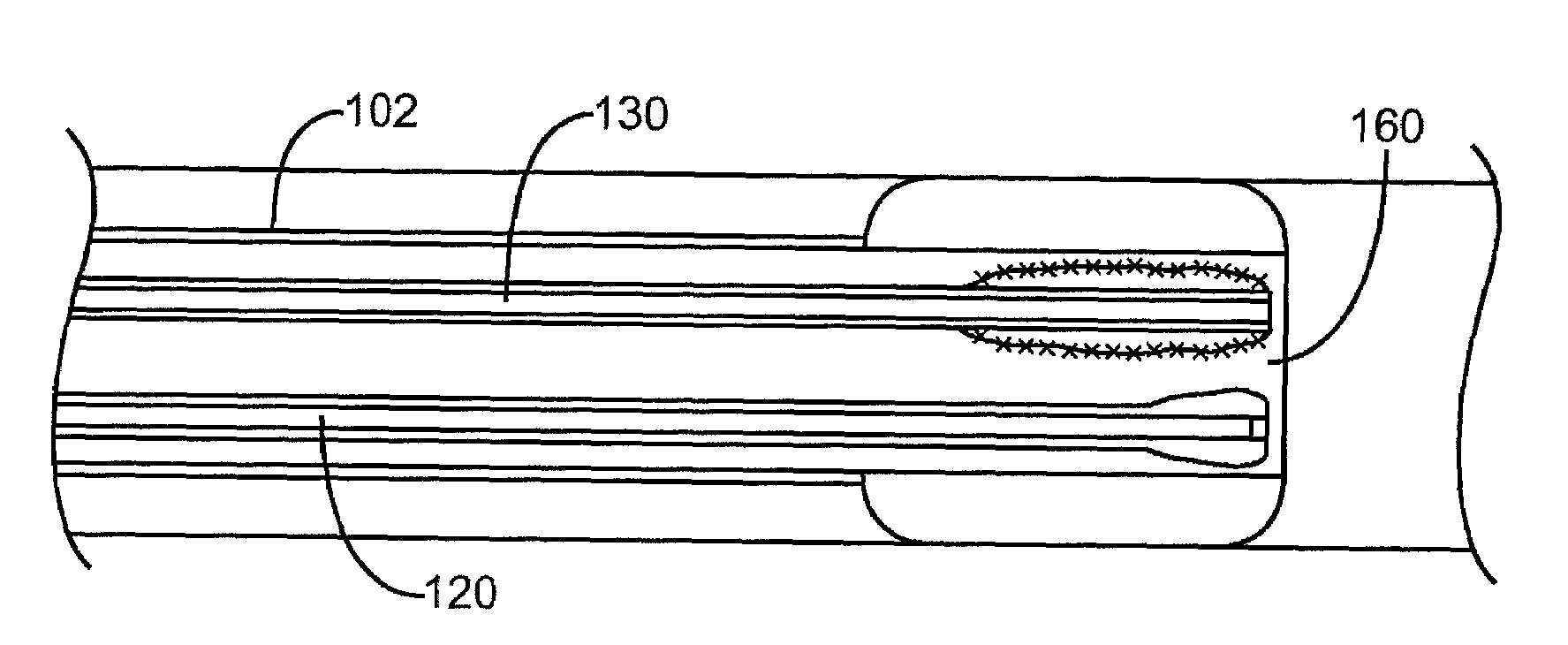
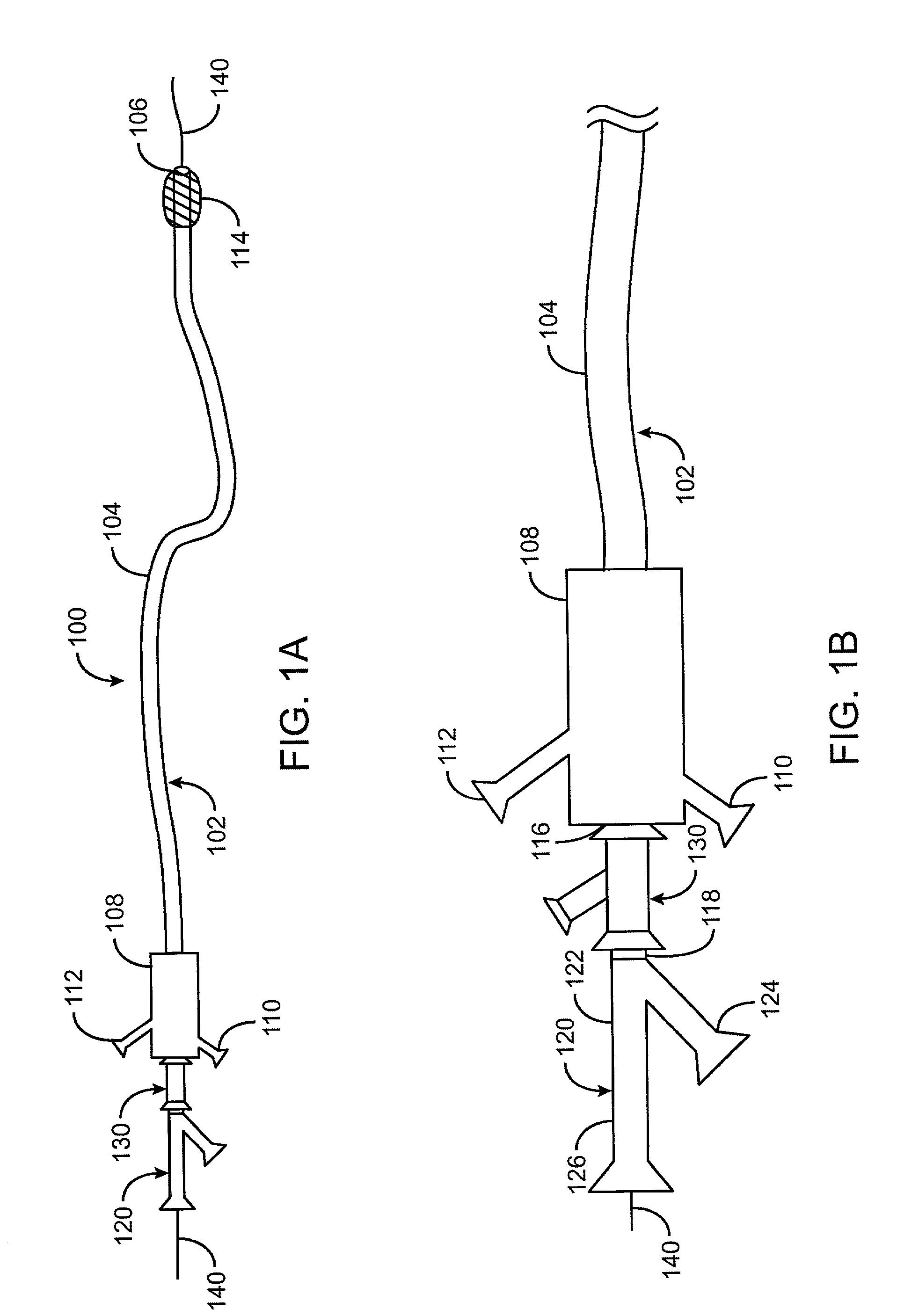
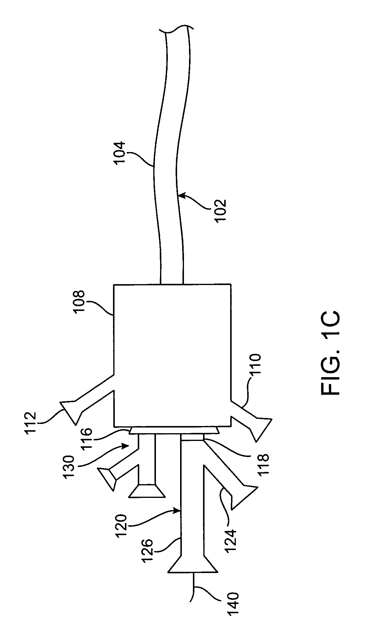
[0039]FIG. 1a is a perspective drawing of an embolization protection system 100 constructed according to the present invention. FIG. 1a shows an outer catheter 102 having an extended shaft 104 with a distal end 106 and a proximal adaptor 108. FIG 1b is a detail drawing of a proximal portion of the catheter system of FIG. 1 showing the proximal adaptor 108. FIG. 11 is a cutaway view showing the coaxial arrangement of the catheter shafts in the distal embolic protection system. The proximal adaptor 108 may be an injection molded part or it may be assembled from separate components. The proximal adaptor 108 has several ports: one is an efflux port 110 where fluid is removed from the suction or efflux lumen 160 of the catheter 102, an optional inflation port 112 in connection with an inflation lumen 162 for inflating an occluding balloon 114 at or near the distal end 104, for those embodiments with either a balloon or self-expanding foam as the occluding mechanism, a treatment port 116 ...


PUM


Abstract

Apparatus and methods are described for effective removal of emboli or harmful fluids during vascular procedures, such as angiography, balloon angioplasty, stent deployment, laser angioplasty, atherectomy, intravascular ultrasonography and other therapeutic and diagnostic procedures. A catheter with an occluder mounted at its distal end creates an occlusion proximal to the lesion. The catheter provides a pathway for introducing a treatment catheter. Prior to, during or subsequent to the procedure, suction is activated to establish retrograde flow to remove emboli from the site. Additionally, a thin catheter with a distal fluid ejection nozzle maybe introduced distal to the treatment site to rinse emboli from the treatment site. The suction flow and / or ejected fluid flow may be varied in a pulsatile manner to simulate regular blood flow and / or perturb settled emboli into being captured that may otherwise not be collected. The method establishes a protective environment before any devices enter the site to be treated.

Description

CROSS-REFERENCE TO OTHER APPLICATIONS[0001]This application claims the benefit of U.S. Provisional Patent Application No. 60 / 208,953, filed May 31, 2000.FIELD OF THE INVENTION[0002]This invention relates to the field of medical procedures on vessels of the circulatory system including catheter-based or other minimally invasive procedures. Sites within the vasculature at which the current invention may be employed include the carotid arteries, saphenous vein bypass grafts, and the renal arteries as well as other sites where harmful agents, such as emboli and radiopaque dyes, may be created or introduced during treatment and retrograde flow combined with a brief period of circulatory occlusion can be tolerated.BACKGROUND OF THE INVENTION[0003]The ability to effectively remove emboli and / or contrast agents during medical procedures in the circulatory system would have broad implications on how vascular disease and conditions are treated and complications are managed.[0004]The use of pr...

Claims


Application Information

Patent Timeline
IPC IPC(8): A61M29/00A61B17/22A61F2/01A61M25/00A61M25/10
CPCA61B17/22A61B17/22031A61F2/013A61B2017/22067A61B2017/22082A61F2230/0006A61F2230/008A61F2002/018A61B2017/22084
Inventor COURTNEY, BRIAN K.MACMAHON, JOHN M.GOFF, THOMAS G.
Owner CHINE LLC
Learn More