Device and method of a back EMF permanent electromagnetic motor generator

a permanent electromagnetic motor and generator technology, applied in the direction of motor/generator/converter stopper, dynamo-electric converter control, magnetic bodies, etc., can solve the problems of internal losses and inefficiencies, internal losses, and input energy always lost in the motor itsel

a permanent electromagnetic motor and generator technology, applied in the direction of motor/generator/converter stopper, dynamo-electric converter control, magnetic bodies, etc., can solve the problems of internal losses and inefficiencies, internal losses, and input energy always lost in the motor itsel

US7109671B2Inactive Publication Date: 2006-09-19ENERGENX

Image

  • Device and method of a back EMF permanent electromagnetic motor generator
  • Device and method of a back EMF permanent electromagnetic motor generator
  • Device and method of a back EMF permanent electromagnetic motor generator

Examples


Embodiment Construction

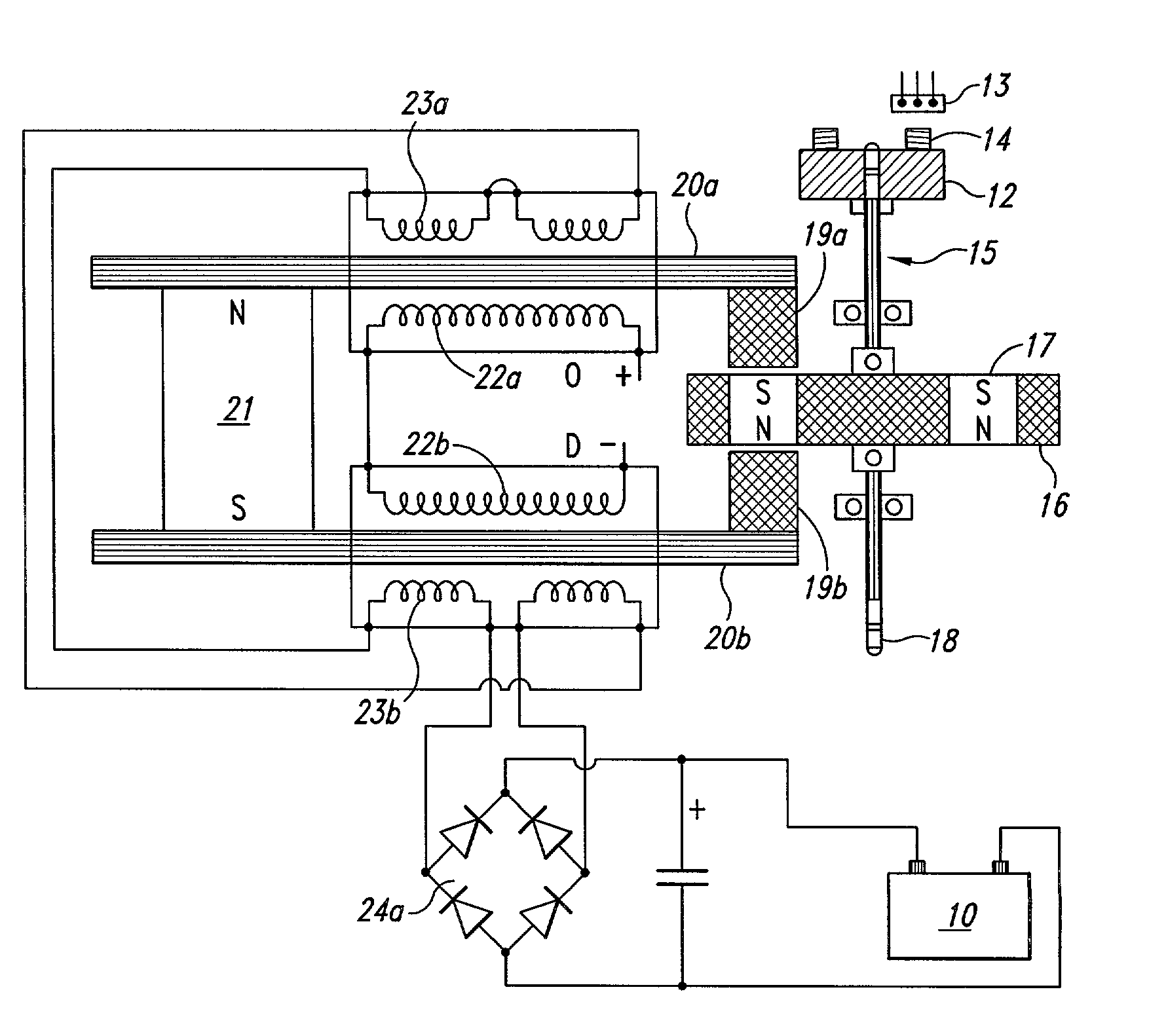
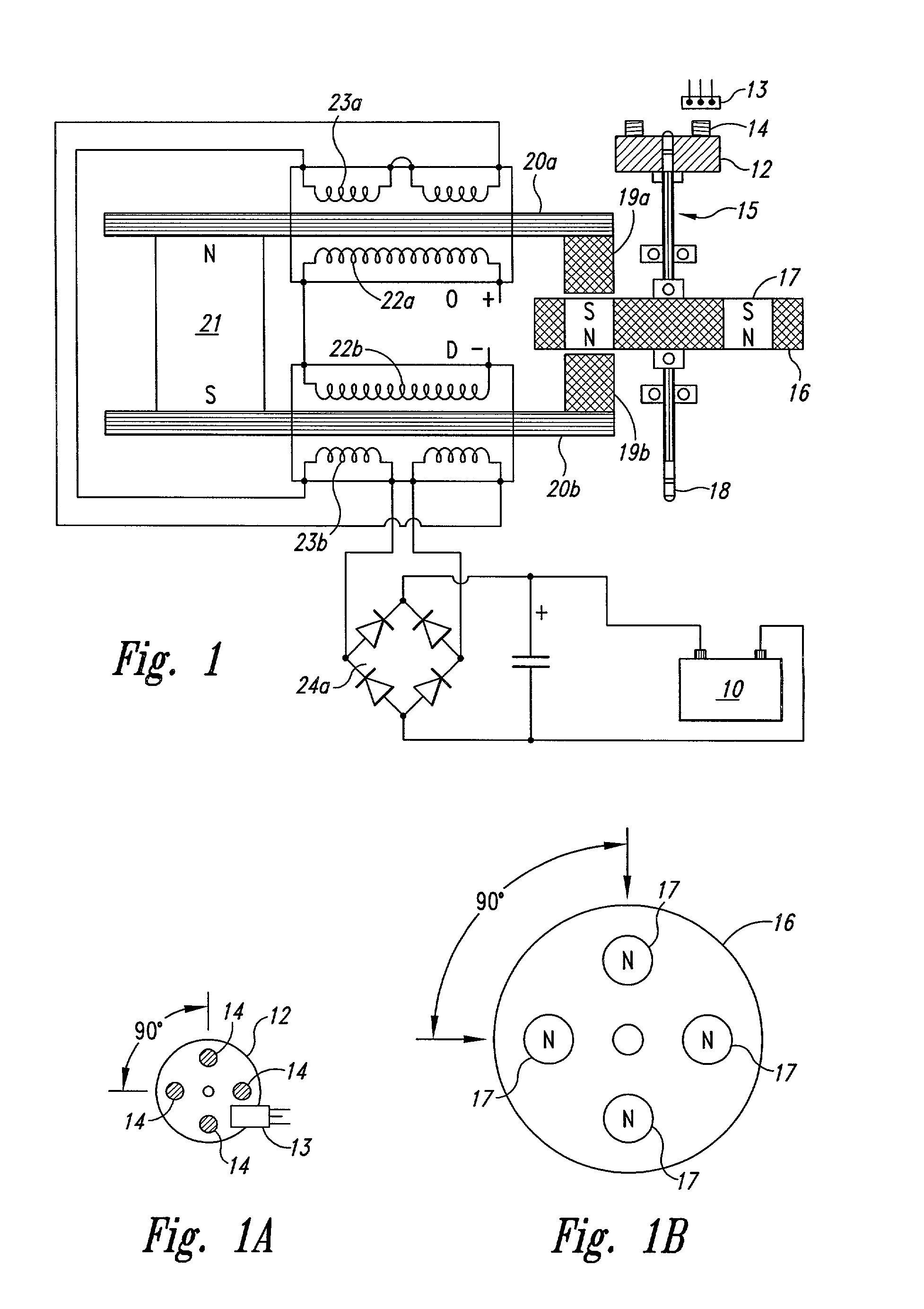
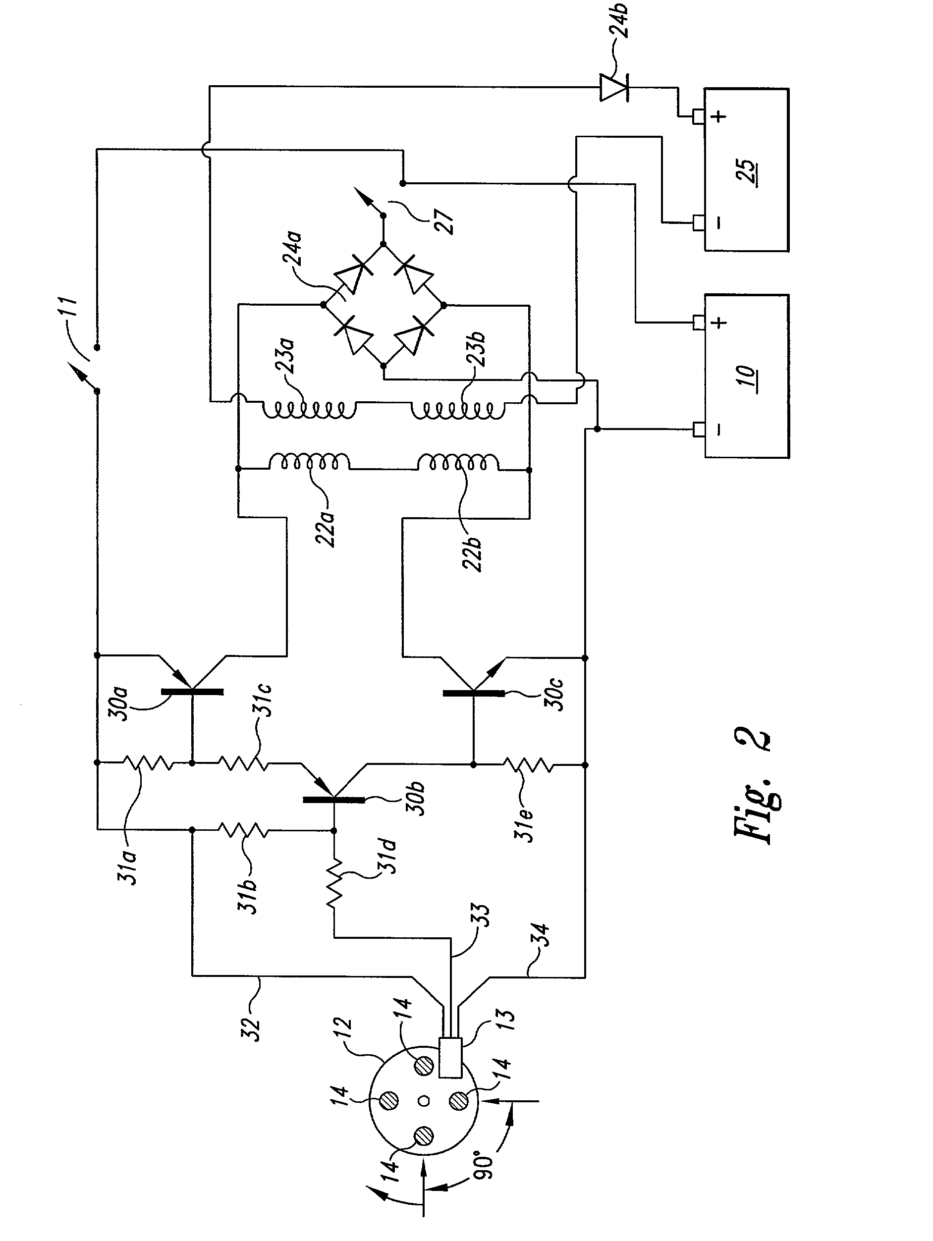
[0072]The present invention is a device and method for creating a back EMF permanent electromagnetic motor generator. As described in the Background Information, this new motor generator conforms to all applicable electrodynamic laws of physics and is in harmony with the law of the conservation of energy, the laws of electromagnetism and other related natural laws.

[0073]The back EMF permanent electromagnetic motor generator is comprised of combination of electrical, material and magnetic elements to capture available electromagnetic energy (back EMF) in a recovery rectifier or single diode from output coils. The capturing of back EMF energy is also known as regauging in the art. As an arbitrary starting point in describing this invention, an input battery, as a means of energy, sends power through a power on-off switch and then to a means for timing such as a magnetic timing switch (Hall Effect magnetic pickup switch, a semiconductor) which interfaces with or is in apposition to a m...


PUM


Abstract

This invention is a back EMF permanent electromagnetic motor generator and method using a regauging process for capturing available electromagnetic energy in the system. The device is comprised of a rotor with magnets of the same polarity; a timing wheel in apposition to a magnetic Hall Effect pickup switch semiconductor; and a stator comprised of two bars connected by a permanent magnet with magnetized pole pieces at one end of each bar. There are input and output coils created by wrapping each bar with a conducting material such as copper wire. Energy from the output coils is transferred to a recovery rectifier or diode. The magnets of the rotor, which is located on a shaft along with the timing wheel, are in apposition to the magnetized pole pieces of the two bars. The invention works through a process of regauging, that is, the flux fields created by the coils is collapsed because of a reversal of the magnetic field in the magnetized pole pieces thus allowing the capture of available back EMF energy. Additional available energy may be captured and used to re-energize the battery, and / or sent in another direction to be used as work. As an alternative, the available back EMF energy may be dissipated into the system.

Description

BACKGROUND OF THE INVENTION[0001]1. Field of the Invention[0002]The invention relates generally to the capturing of electromagnetic energy using a method and device to create back EMF (electromagnetic force) and re-phasing of the back EMF to recycle and capture the available back EMF energy. Back EMF is also referred to as regauging and may be defined as energy created by the magnetic field from coils, and only by coils, and not by magnets.[0003]2. Background Information and Related Art[0004]Operation of a normal magnetic motor has the rotor pole attracting the stator pole, resulting in the generation of power from the magnets to the rotor and flywheel. During this phase, energy flows from the magnetics to the rotor / flywheel and is stored in the increased rotation. A rotor pole leaving a stator pole and creating a condition of drag-back results in power having to be put back into the magnetic section by the rotor and flywheel to forcibly overcome the drag-back. In a perfect, frictio...

Claims


Application Information

Patent Timeline
19 Sep 2006
Publication
US7109671B2
IPC
H02K47/14; H02K21/00; H02K29/08; H02K53/00; H02P9/00
CPC
H02K21/24; H02P9/00; H02K53/00; H02K29/08
Inventors
BEDINI, JOHN C.