Liquefied natural gas storage tank

Inactive Publication Date: 2006-09-26
EXXONMOBIL UPSTREAM RES CO
View PDF60 Cites 30 Cited by
  • Summary
  • Abstract
  • Description
  • Claims
  • Application Information

AI Technical Summary

Benefits of technology

[0022]By using an internal truss frame structure and/or the plate girder ring frame structure in one embodiment of the invention to provide the primary support for the tank, the interior of the tank may be effectively contiguous throughout without any encumbrances provided by any bulkheads or the like. This permits the relatively long interior of the tank of this invention to avoid resonance conditions during sloshing under the substantially different dynamic loading caused by seismic activity as opposed to the loading that occurs due to the motion of a sea-going vessel.
[0023]In contrast to published designs of rectangular liquid storage tanks, which teach away from reinforcement and stiffening of t

Problems solved by technology

While structurally efficient, circular cylindrical tanks in their state-of-practice designs are difficult and time consuming to build.
Typically, membrane tanks take just as long or longer to build.
On many projects, this causes undesirable escalation of construction costs and length of construction schedule.
Unfortunately, neither cylindrical tanks nor membrane tanks are considered as being particularly attractive for use in storing LNG on GBS terminals.
Cylindrical tanks typically do not store enough LNG to economically justify the amount of room such tanks occupy on a GBS and are difficult and expensive to construct on a GBS.
This necessitates a multiplicity of storage units to satisfy particular storage requirements, which is typically not desirable from cost and other operational considerations.
However, a membrane-type tank requires a sequential construction schedule wherein the outer concrete structure has to be completely built before the insulat

Method used


Image

  • Liquefied natural gas storage tank
  • Liquefied natural gas storage tank
  • Liquefied natural gas storage tank

Examples


Embodiment Construction

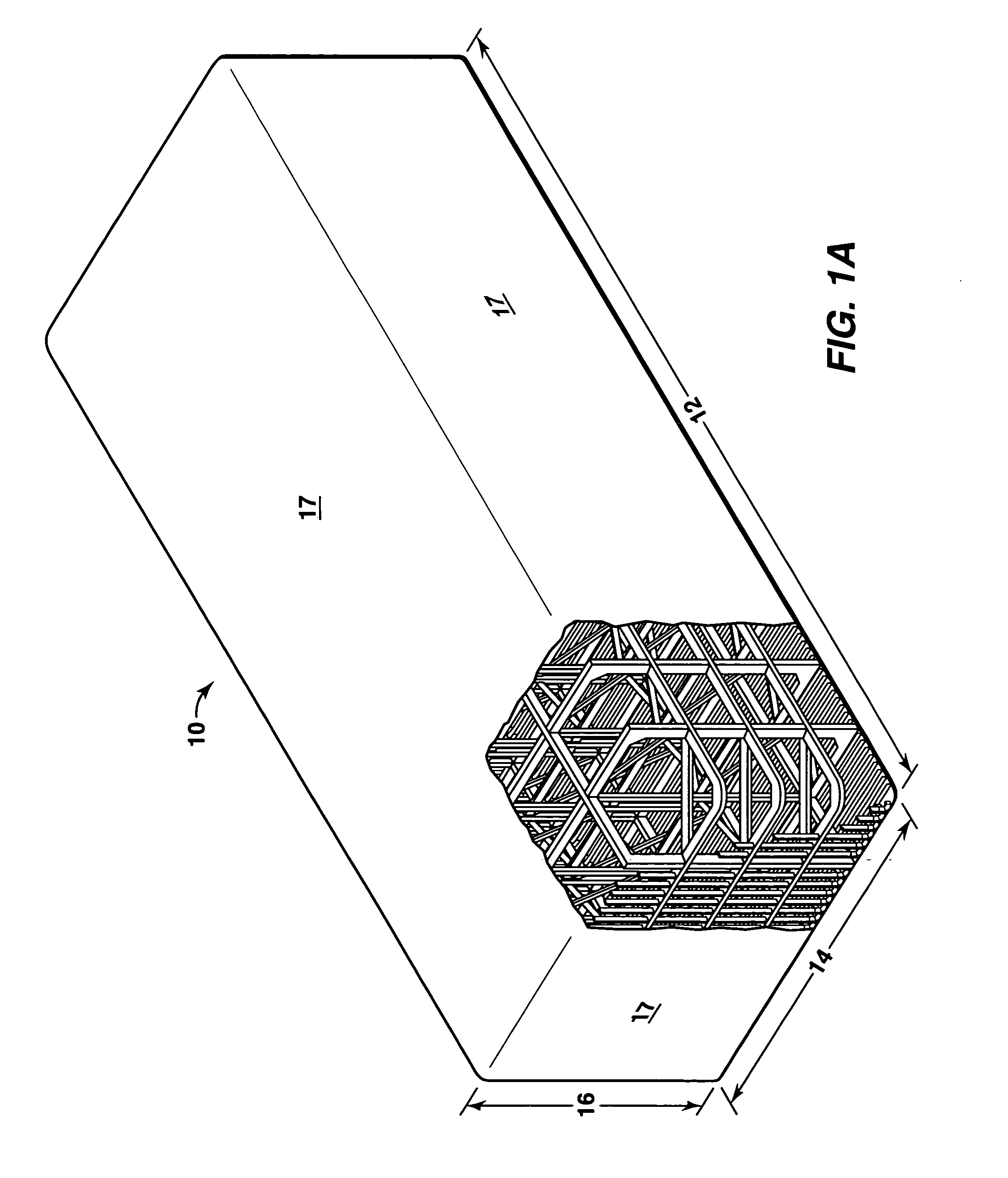
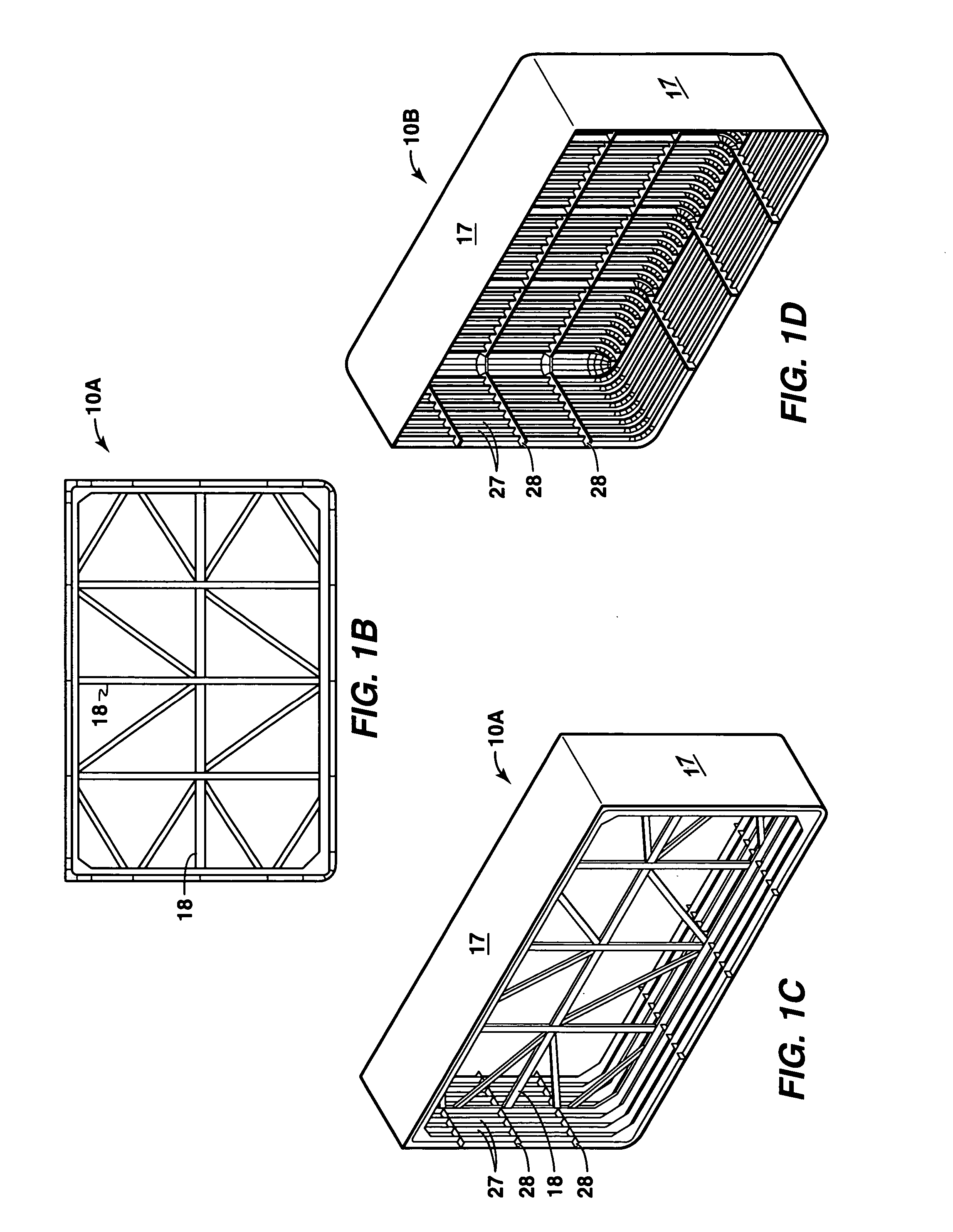
[0043]A substantially rectangular-shaped storage tank of a preferred embodiment of the present invention is designed to provide the ability to vary capacity of the tank, in discrete steps, without a substantial redesign of the tank. Solely for construction purposes, this is achieved by considering the tank as comprising a number of similar structural modules. For example, a 100,000 meter3 tank may be considered to comprise four substantially equal structural modules obtained by cutting a large tank by three imaginary vertical planes suitably spaced along the length direction such that each section is conceptually able to hold approximately 25,000 meter3 of liquid. Such a tank is comprised of two substantially identical end sections and two substantially identical mid sections. By removing or adding mid sections during construction of the tank, tanks of same cross-section, i.e., same height and width, but variable length and thus variable capacity, in discrete steps, can be obtained....


PUM


Abstract

Substantially rectangular-shaped tanks are provided for storing liquefied gas, which tanks are especially adapted for use on land or in combination with bottom-supported offshore structure such as gravity-based structures (GBS). A tank according to this invention is capable of storing fluids at substantially atmospheric pressure and has a plate cover adapted to contain fluids and to transfer local loads caused by contact of said plate cover with said contained fluids to an internal frame structure comprised of a plate girder ring frame structure and/or an internal truss frame structure. Optionally, a grillage of stiffeners and stringers may be disposed on the plate cover and additional sifters disposed on the plate girder ring frame structure and/or an internal truss frame structure. Methods of constructing these tanks are also provided.

Description

CROSS REFERENCE TO RELATED APPLICATIONS[0001]This application is a continuation-in-part of U.S. application Ser. No. 09 / 876,684, filed 7 Jun. 2001, now U.S. Pat. No. 6,729,492 which is a continuation-in-part of U.S. application Ser. No. 09 / 256,383, filed 24 Feb. 1999, now U.S. Pat. No. 6,732,881 which claims the benefit of U.S. Provisional Application No. 60 / 104,325, filed 15 Oct. 1998.FIELD OF THE INVENTION[0002]The present invention relates to liquefied gas storage tanks and in one aspect relates to tanks especially adapted for storing liquefied gases at cryogenic temperatures at near atmospheric pressures (e.g., liquefied natural gas (“LNG ”)).BACKGROUND OF THE INVENTION[0003]Various terms are defined in the following specification. For convenience, a Glossary of terms is provided herein, immediately preceding the claims.[0004]Liquefied natural gas (LNG) is typically stored at cryogenic temperatures of about −162° C. (−260° F.) and at substantially atmospheric pressure. As used h...

Claims


Application Information

Patent Timeline
IPC IPC(8): F17C1/00F17C13/00F17C3/00B65D88/10B65D90/02F17C3/02
CPCF17C3/00F17C3/025F17C13/004B65D88/10Y10S220/901F17C2201/0157F17C2201/035F17C2201/052F17C2201/054F17C2203/01F17C2203/012F17C2203/013F17C2203/0304F17C2203/0617F17C2203/0629F17C2203/0636F17C2203/0639F17C2203/0643F17C2203/0646F17C2203/0648F17C2203/0678F17C2205/0184F17C2209/22F17C2209/221F17C2209/228F17C2221/033F17C2223/0161F17C2223/033F17C2260/011F17C2260/012F17C2260/013F17C2260/016F17C2270/0105F17C2270/0113F17C2270/0118F17C2270/0121F17C2270/0134F17C2270/0136B65D90/023F17C1/00F17C13/00
Inventor GULATI, KAILASH C.MOON, RAYMOND
Owner EXXONMOBIL UPSTREAM RES CO
Why Eureka
Try Eureka