Vacuum carbo-nitriding method

Inactive Publication Date: 2006-09-26
KOYO THERMO SYST CO LTD
View PDF6 Cites 14 Cited by
  • Summary
  • Abstract
  • Description
  • Claims
  • Application Information

AI Technical Summary

Benefits of technology

[0009]According to the vacuum carbonitriding method of claim 1, even in the case of a workpiece made of low-grade steel, it is possible to improve the surface hardness by preventing the amount of retained austenite in the surface layer from becoming excessive, as well as to increase the effective case depth in a relatively short time. In addition,

Problems solved by technology

In the conventional method, however, when the vacuum carburization is performed while disposing a basket which carries a number of objects to be treated (workpieces) in an effective heating space where uniformity of temperature is ensured in the vacuum heat treating furnace, there arises a problem that unevenness of carburization occurs in the workpieces depending on the carried position in the basket, and variation occurs in carburization quality such as effective case depth (carburization depth) and surface carbon concentration among workpieces in different carried positions.
In the method disclosed in Japanese Unexamined Patent Publication No. 2001-262313, however, low grade steels, for example, steels containing a high proportion of impurities such as MnS, low alloy steels, low carbon steels and the like would not be hardene

Method used


Image

  • Vacuum carbo-nitriding method
  • Vacuum carbo-nitriding method
  • Vacuum carbo-nitriding method

Examples


example 1

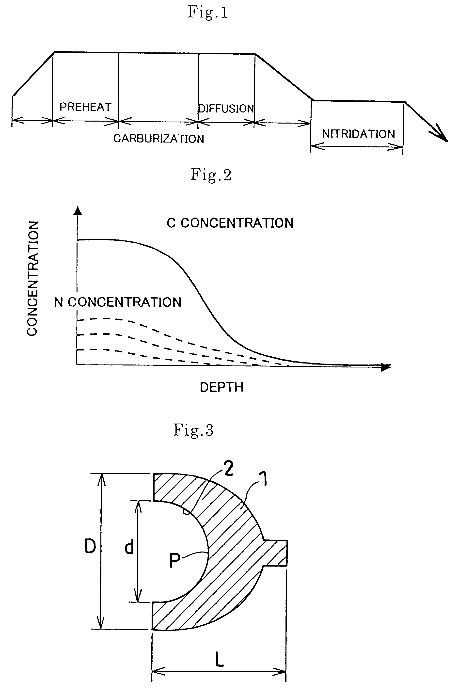
[0027]A plurality of cup ends (1) were loaded in the lower basket of two baskets piled in such a manner that the opening of the recess (2) was directed downward, while a plurality of dummies were loaded in the upper basket of the two baskets piled. The baskets piled were then disposed in an effective heating space where uniformity of temperature was secured in a vacuum heat treating furnace. The total weight of the cup ends (1) was 17.5 kg, the total weight of the cup ends, dummies, baskets and tray was 75.5 kg.

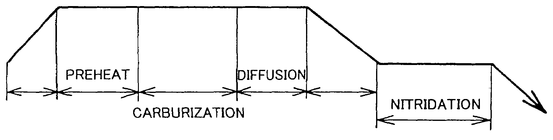
[0028]Then after reducing the pressure of the interior of the vacuum heat treating furnace to 0.14 kPa or less over 8 minutes, the effective heating space in the furnace was heated to 930° C. over 14 minutes, and kept at this temperature for 40 minutes so as to perform a preheating process. Subsequent to the preheating process, a carburizing process was performed which involves keeping at 930° C. for 100 minutes under the pressure of 7 to 8 kPa while supplying the heat treati...

example 2

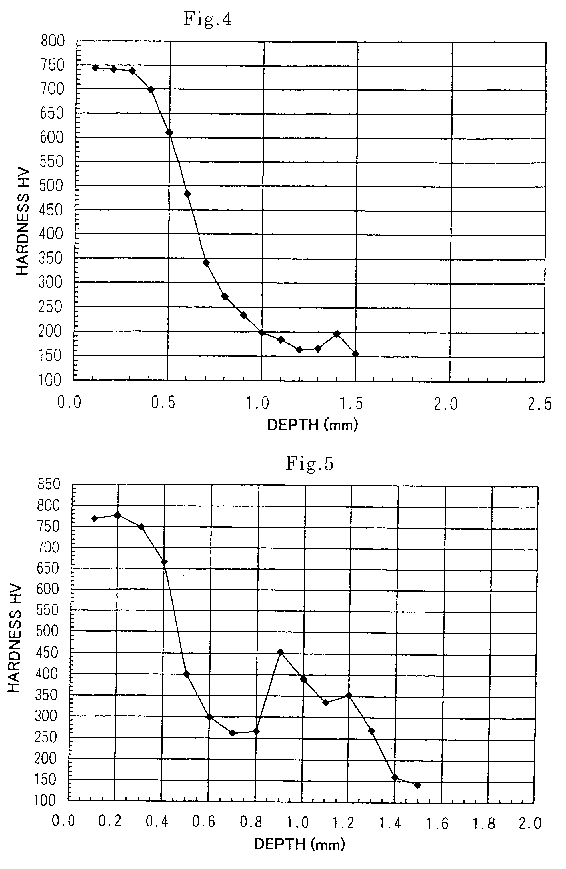
[0029]The vacuum carbonitriding process was performed on the cup ends (1) in the same manner as in Example 1 except that the nitriding time was changed to 120 minutes.

example 3

[0030]The vacuum carbonitriding process was performed on the cup ends (1) in the same manner as in Example 1 except that the nitriding time was changed to 60 minutes.


PUM

PropertyMeasurementUnit
Temperatureaaaaaaaaaa
Pressureaaaaaaaaaa

Abstract

A vacuum carbonitriding method includes: performing a vacuum carburizing process on an object to be treated (a workpiece) in a heat treating furnace under reduced pressures by supplying a carburizing gas into the furnace that has been heated to a predetermined carburizing temperature; stopping supply of the carburizing gas while keeping the carburizing temperature so as to diffuse carbon in the workpiece under reduced pressures; and performing a nitriding process on the workpiece by supplying a nitriding gas into the furnace under reduced pressures after lowering the furnace temperature. Required heat treatment qualities such as surface hardness, effective case depth, toughness and the like can be achieved in a short time with reproducibility even in a case of workpiece made of low-grade steel or case-hardened steel.

Description

TECHNICAL FIELD[0001]The present invention relates to a vacuum carbonitriding method performed under reduced pressures.BACKGROUND ART[0002]As a vacuum carburizing method of performing a carburizing process on steel parts for automobile such as gears, bearings, fuel injection nozzles and constant velocity joints, for example, a method of using ethylene gas as a carburizing gas to perform the process under reduced pressures of 1 to 10 kPa in a vacuum heat treating furnace has been known (see Japanese Unexamined Patent Publication No. 11-315363).[0003]In the conventional method, however, when the vacuum carburization is performed while disposing a basket which carries a number of objects to be treated (workpieces) in an effective heating space where uniformity of temperature is ensured in the vacuum heat treating furnace, there arises a problem that unevenness of carburization occurs in the workpieces depending on the carried position in the basket, and variation occurs in carburizatio...

Claims


Application Information

Patent Timeline
IPC IPC(8): C23C8/34C23C8/30C23C8/32
CPCC23C8/30C23C8/34C23C8/32
Inventor YAMAGUCHI, KAZUYOSHI
Owner KOYO THERMO SYST CO LTD
Why Eureka
Try Eureka