
Method of making components with releasable leads

Inactive Publication Date: 2006-10-03
TESSERA INC
View PDF57 Cites 18 Cited by
  • Summary
  • Abstract
  • Description
  • Claims
  • Application Information

AI Technical Summary

Benefits of technology

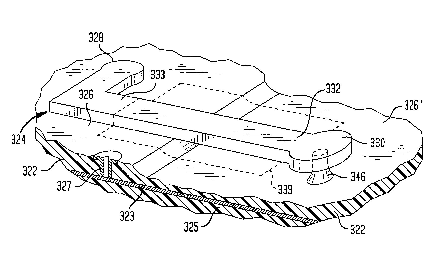
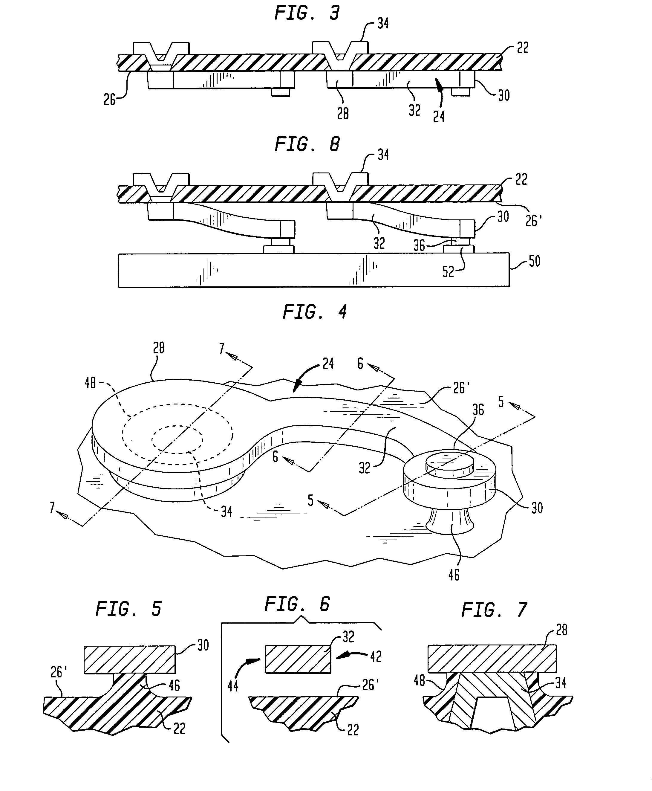
[0012]The polymeric connection regions or connecting elements provide reliable, readily releasable connections between the attachment regions of the leads and the dielectric layer. Regardless of the degree of adhesion between the polymeric layer and the material of the leads, the force required to release a connection cannot exceed the tensile strength of the polymeric connecting element. This is controlled by the cross-sectional area of the polymeric connecting element. This area can be controlled accurately in the etching process.
[0018]The insulated leads provide immunity to accidental short-circuiting during or after connection with the microelectronic component. In the embodiment incorporating the conductive jackets, the leads act as miniature coaxial cables, and provide well-controlled impedance which enhances signal propagation and permits operation at high frequencies. The miniature coaxial cables also provide outstanding immunity to electromagnetic interference such as cross-talk between adjacent leads. In a further variant, each lead and the surrounding conductive jacket may serve as the two conductors of a differential signaling circuit.

Problems solved by technology

Thus, although the base metal may provide a relatively high bond strength per unit area or per unit length, it may still provide a weak attachment of the tip end of the lead end to the first element surface.

Method used


Image

  • Method of making components with releasable leads
  • Method of making components with releasable leads
  • Method of making components with releasable leads

Examples


Embodiment Construction

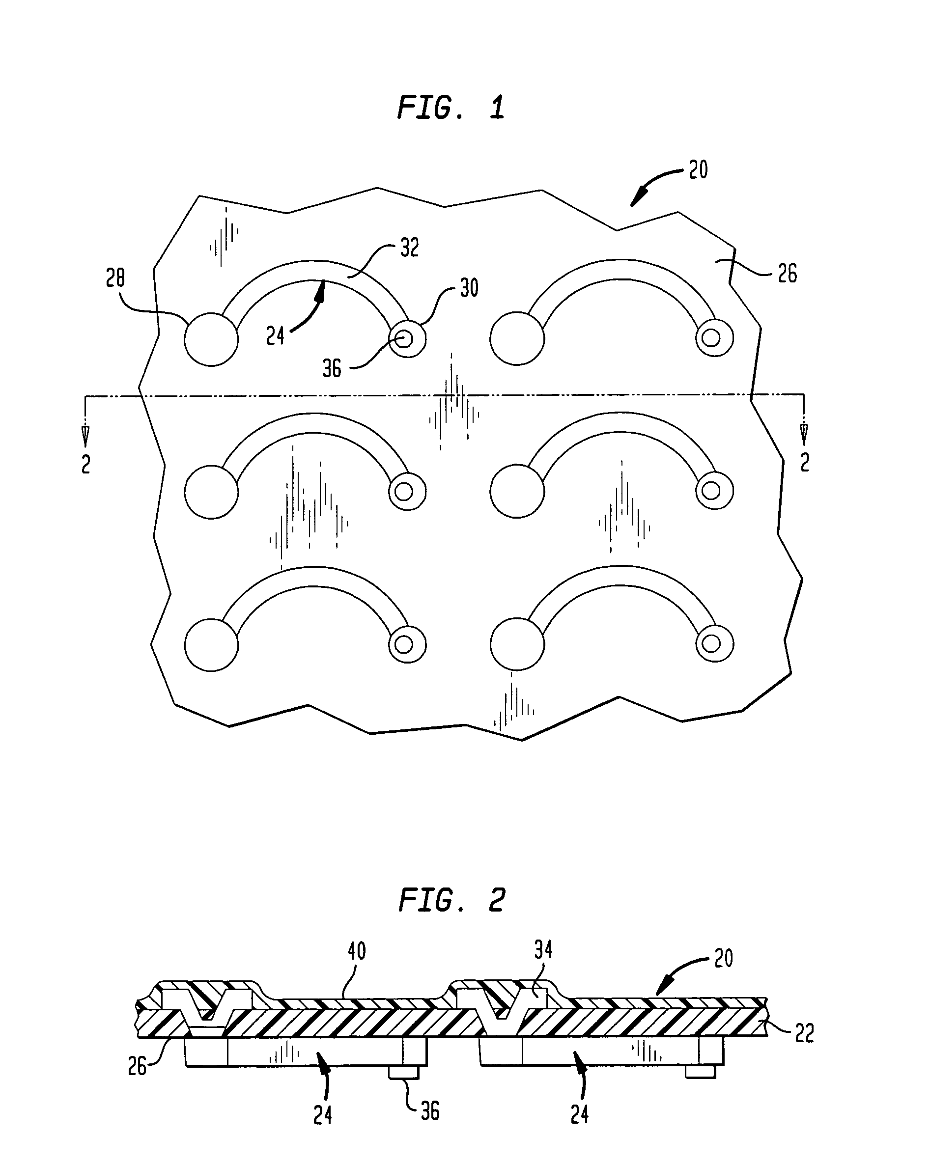
[0042]A process in accordance with one embodiment of the invention begins with a starting structure 20 incorporating a dielectric layer, preferably a polymeric layer 22 and a plurality of leads 24 overlying a surface 26 of the dielectric layer. Each lead includes a first end 28, a second end 30 and a relatively narrow, elongated section 32 extending between the ends. The first end 28 of each lead is wider than elongated section 32, and the second end 30 of each lead is also wider than the elongated section. Stated another way, the minimum distance across each lead at the ends is greater than the minimum distance across the lead within elongated section 32. The leads adhere to the surface 26 of layer 22. Additionally, the first end 28 of each lead is physically attached to the polymeric layer by a metallic electrical conductor 34 extending into the polymeric layer at the first end.

[0043]Dielectric layer 22 may be formed by essentially any polymeric material which can be etched by the...


PUM

PropertyMeasurementUnit
Lengthaaaaaaaaaa
Dielectric polarization enthalpyaaaaaaaaaa
Electrical conductivityaaaaaaaaaa

Abstract

A connection component for making connections to a microelectronic element is made by providing leads on a surface of a polymeric layer and etching the polymeric layer to partially detach the leads from the polymeric layer, leaving a portion of each lead releasably connected to the polymeric layer by a small polymeric connecting element which can be broken or peeled away from the lead. Leads in a connecting element may be covered by an insulating jacket applied by a coating process, and the insulating jacket may in turn be covered by a conductive layer so that each lead becomes a miniature coaxial cable. This arrangement provides immunity to interference and facilitates operation at high speeds.

Description

CROSS-REFERENCE TO RELATED APPLICATIONS[0001]The present application is a continuation of U.S. patent application Ser. No. 10 / 366,425, filed Feb. 13, 2003, now U.S. Pat. No. 6,763,579 which application is a divisional of U.S. patent application Ser. No. 09 / 549,638, filed Apr. 14, 2000, now U.S. Pat. No. 6,557,253, which is a continuation of U.S. patent application Ser. No. 09 / 020,750, filed Feb. 9, 1998, now abandoned the disclosure of which is hereby incorporated by reference herein.FIELD OF THE INVENTION[0002]The present invention relates to components useful in making electrical connections to microelectronic elements such as semiconductor chips, and to methods of manufacturing such components.BACKGROUND OF THE INVENTION[0003]Certain techniques for making semiconductor chip assemblies and similar microelectronic assemblies employ releasably attached leads. One such process is disclosed in commonly assigned U.S. Pat. No. 5,518,964, the disclosure of which is hereby incorporated by...

Claims


Application Information

Patent Timeline
IPC IPC(8): H01R9/00H01L23/32H05K3/40
CPCH01L23/32H05K3/4092Y10T29/49224H01L2924/01005H01L2924/01006H01L2924/0002H01L2924/3011Y10T29/49149Y10T29/49155Y10T29/49121Y10T29/49147Y10T29/49218Y10T29/49153Y10T29/49222Y10T29/49204H01L2924/00
Inventor HABA, BELGACEMKARAVAKIS, KONSTANTINE
Owner TESSERA INC
Learn More