Abrasive cutting disk with lateral steel sheets

a cutting disk and lateral steel technology, applied in the field of cutting off wheels, can solve the problems of inability to distribute clamping forces over a large area, inability to solve the problem of stable and lasting combination of metallic internal area and external abrasive area, and very thin wheels relative to their diameter

Inactive Publication Date: 2006-10-03
TYROLIT SCHLEIFMITTELWERKE SWAROVSKI KG
View PDF15 Cites 11 Cited by
  • Summary
  • Abstract
  • Description
  • Claims
  • Application Information

AI Technical Summary

Benefits of technology

[0006]The object of the present invention is therefore to create a cutting-off wheel which runs in a stable manner in spite of a w

Problems solved by technology

By reducing the wheel thickness the problem then arises that wheels which are very thin relative to their diameter have a tendency to wobble.
The problem of a stable and lasting combination of metallic inte

Method used


Image

  • Abrasive cutting disk with lateral steel sheets
  • Abrasive cutting disk with lateral steel sheets
  • Abrasive cutting disk with lateral steel sheets

Examples


Embodiment Construction

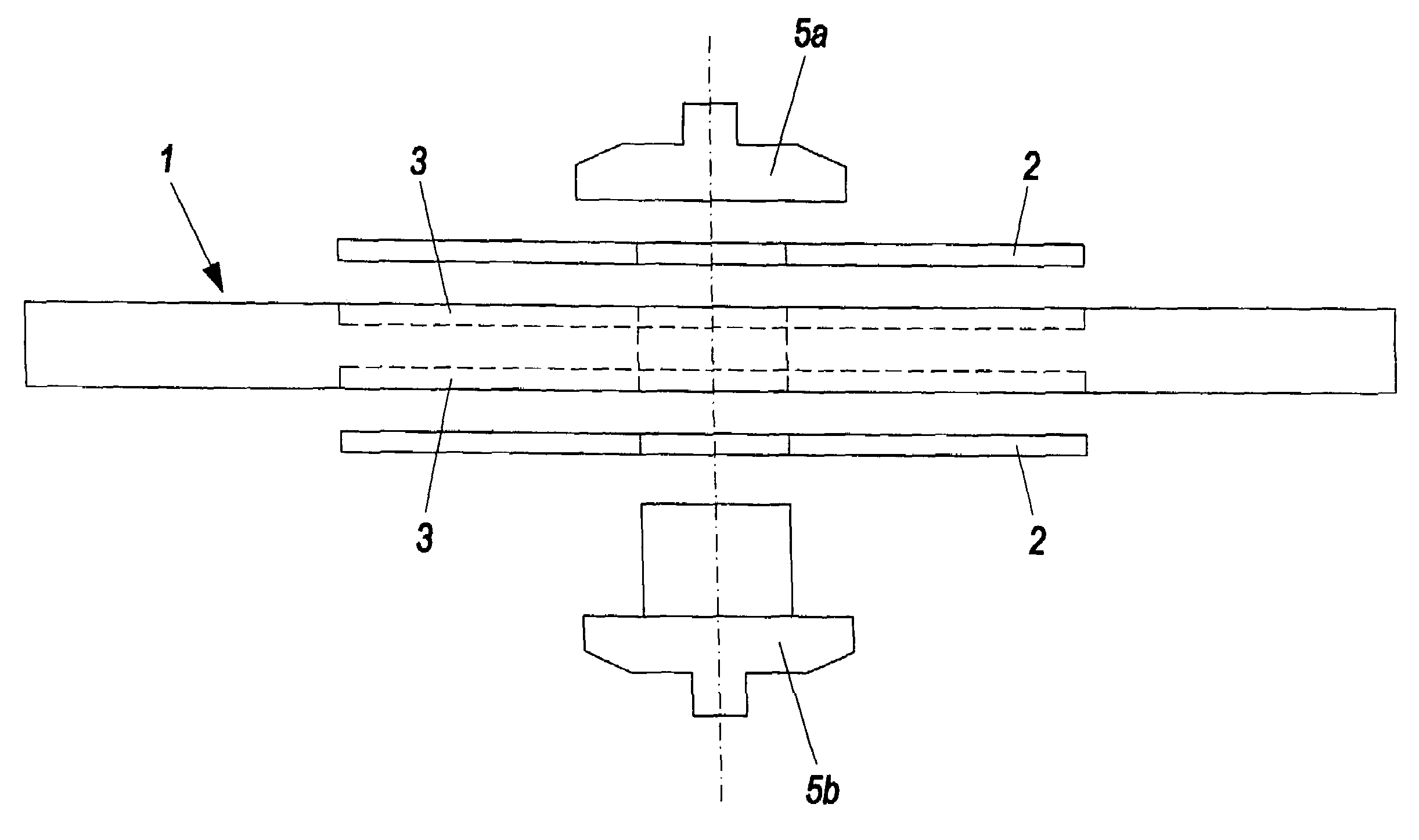
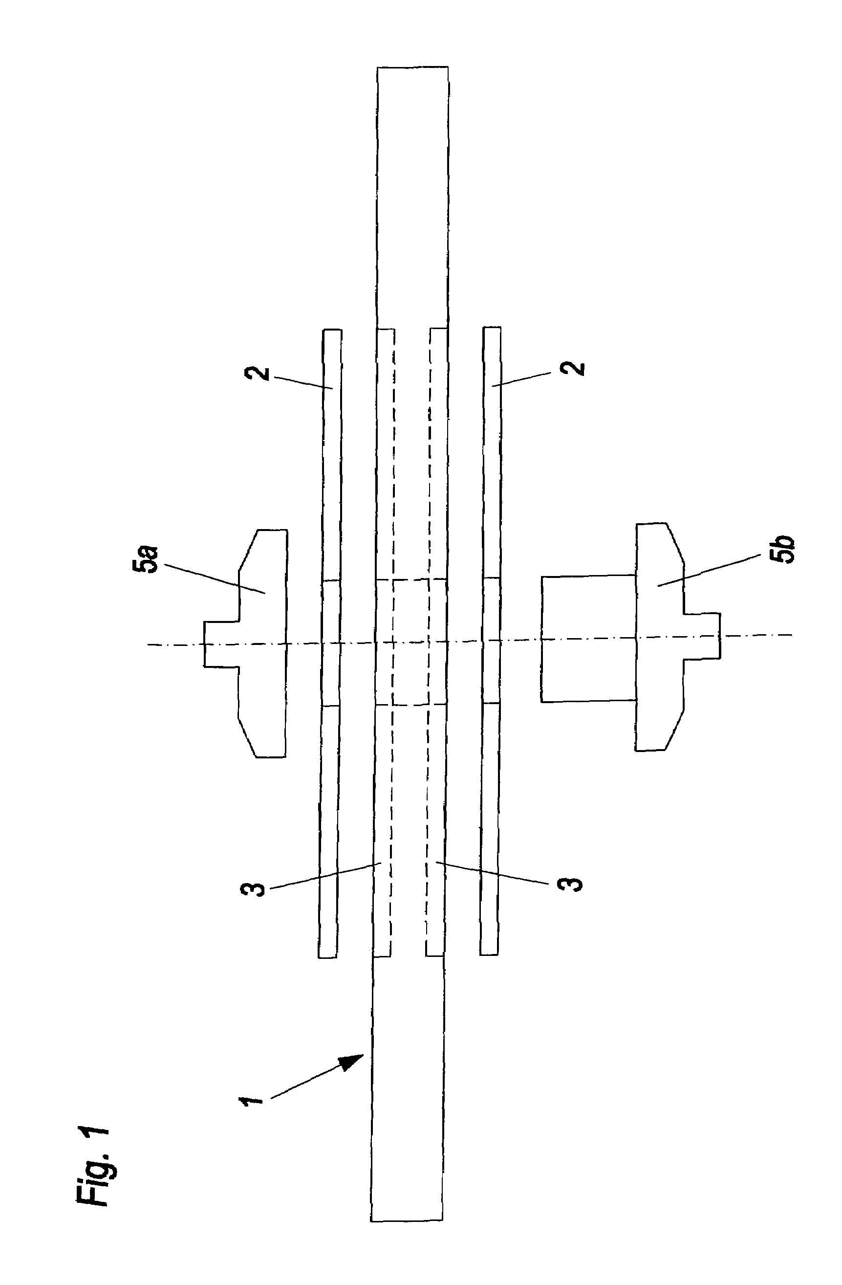
[0018]The cutting-off wheel 1 represented in the Figures is a synthetic-resin-bonded abrasive wheel. Different phenol resins are used as synthetic resin, the targeted selection of which together with the selection of the abrasive and the fillers, ensures that the abrasion behaviour and the degree of hardness of the cutting-off wheel is adapted to the respective requirements.

[0019]Conventional abrasives such as silicon carbide and corundum are preferably used as abrasives. Solid lubricants, for example pyrite and graphite, primarily serve as fillers, as well as customary powdered materials for strengthening plastic such as calcium carbonate or glass powder.

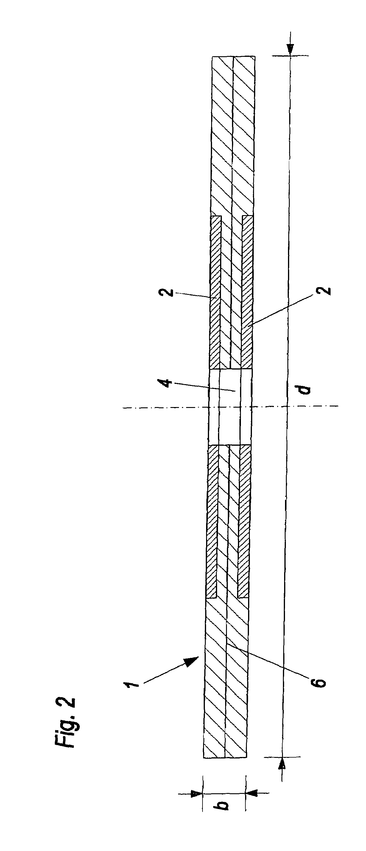
[0020]The diameter d of the cutting-off wheel 1 typically lies between 800 mm and 1800 mm. The proportionality of diameter d to the width b lies above 80, preferably even above 100. This proportionality is to be increased even further on the basis of the present invention. It may be mentioned that the width b of the cutting-off whe...


PUM


Abstract

Cutting-off wheel (1), in particular with a diameter above 500 mm, which is provided laterally with steel sheets or steel grids (2) with a minimum thickness of 0.5 mm.

Description

BACKGROUND OF THE INVENTION[0001]The present invention relates to a cutting-off wheel, with a diameter above 500 mm, which can be clamped between clamping flanges, with a mixture of abrasive grain, binder and optionally fillers, which extends from the outer edge of the cutting-off wheel up to the central bore, the cutting-off wheel being provided laterally with steel sheets or steel grids.[0002]Cutting-off wheels with large diameters are used in the metal-producing industry, where, for example in steel works or foundries, slabs are cut. In this connection it is favourable to keep the wheel thickness of the cutting-off wheel as low as possible in order to keep the cutting losses of the high-quality and expensive metal materials low. In addition, a low wheel thickness means that the power requirement of the cutting-off machine falls as a result of which less load is placed on all mechanical and electrical components of the cutting-off machine with the same cutting-off results.[0003]By...

Claims


Application Information

Patent Timeline
IPC IPC(8): B23F21/03B24D5/12B24D5/16
CPCB24D5/12B24D5/16
Inventor LANG, ADOLFMEISSL, FLORIANBOSIN, MARKUS
Owner TYROLIT SCHLEIFMITTELWERKE SWAROVSKI KG
Why Eureka
Try Eureka