GaN semiconductor based voltage conversion device

a voltage conversion circuit and semiconductor technology, applied in the direction of electric variable regulation, process and machine control, instruments, etc., can solve the problems of electric noise, considerable increase in the size and weight of power supplies, and circuit efficiency, especially at high frequency

Inactive Publication Date: 2006-10-03
POWER INTEGRATIONS INC
View PDF4 Cites 56 Cited by
  • Summary
  • Abstract
  • Description
  • Claims
  • Application Information

AI Technical Summary

Benefits of technology

[0010]A converter is provided having an AC input and a DC output. The converter includes a rectifier that receives the AC input and that provides a rectified output, a series connected, current to magnetic field energy storage device and current interrupter connected across the rectifier output and a series connected gallium nitride diode and output charge storage device connected between a midpoint of the series connected magnetic field energy storage device and current interrupter and a terminal of the rectifier output and wherein the converter is characterized in not needing a transient voltage suppression circuit.

Problems solved by technology

While silicon diodes are inexpensive, they also suffer from a number of disadvantages.
One of the biggest disadvantages is electrical noise.
However, the use of snubber circuitry results in a considerable increase in the size and weight of power supplies.
Another disadvantage is the efficiency of the circuit, especially at high frequency, because of switching losses due to high reverse recovery times in the silicon devices.
However, there are significant disadvantages to the use of SiC.
One of the chief disadvantages of the use of SiC is cost.
The relatively high cost makes the construction of power supplies with SiC diodes commercially unacceptable.
On the one hand, the use of SiC diodes in portable power supplies makes those power supplies smaller and lighter.
On the other hand, the use of Si PiN diodes makes a power supply too heavy and may run hotter.
In addition, where SiC diodes have been described, their use has been limited.
However, prior uses of GaN has been limited to light emitting diodes (LEDs).

Method used


Image

  • GaN semiconductor based voltage conversion device
  • GaN semiconductor based voltage conversion device
  • GaN semiconductor based voltage conversion device

Examples


Embodiment Construction

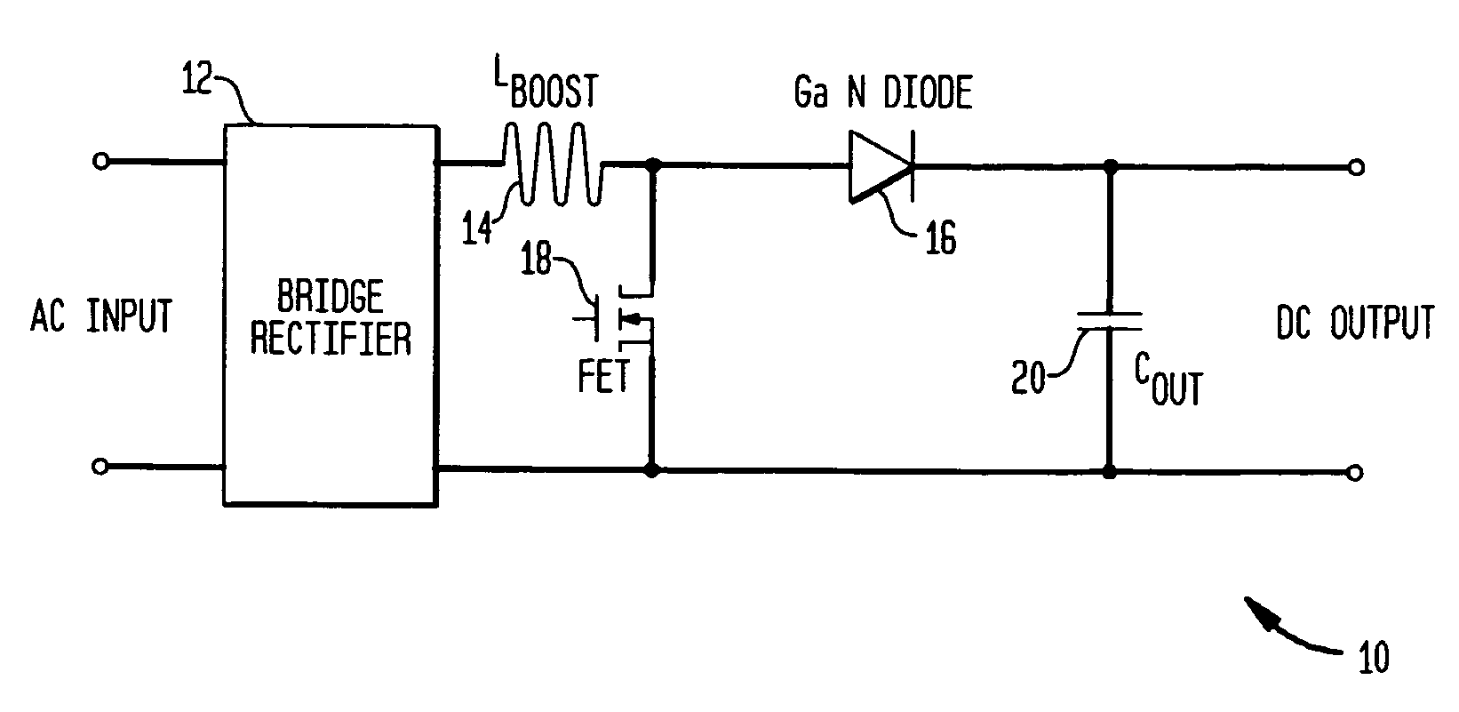
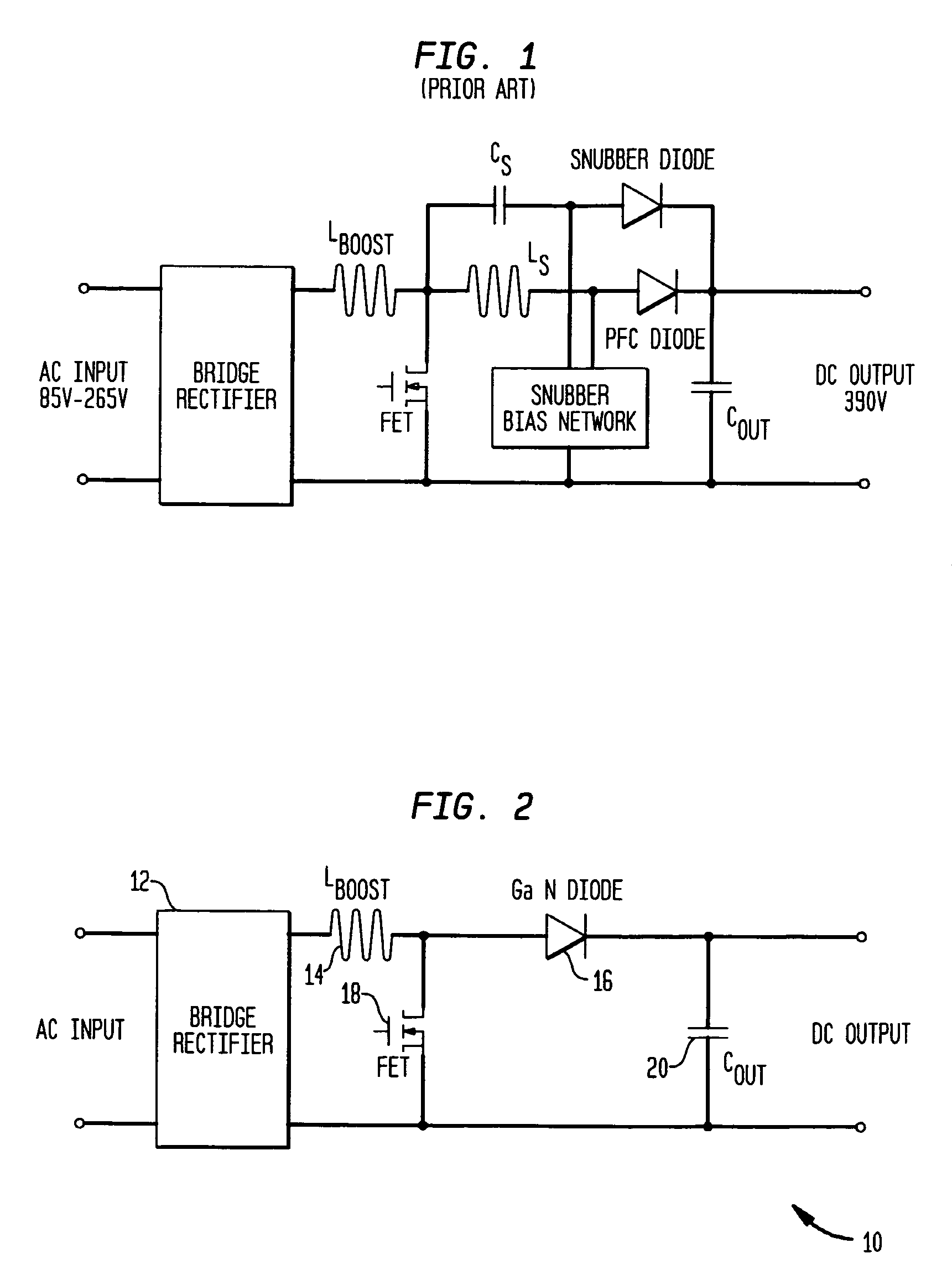
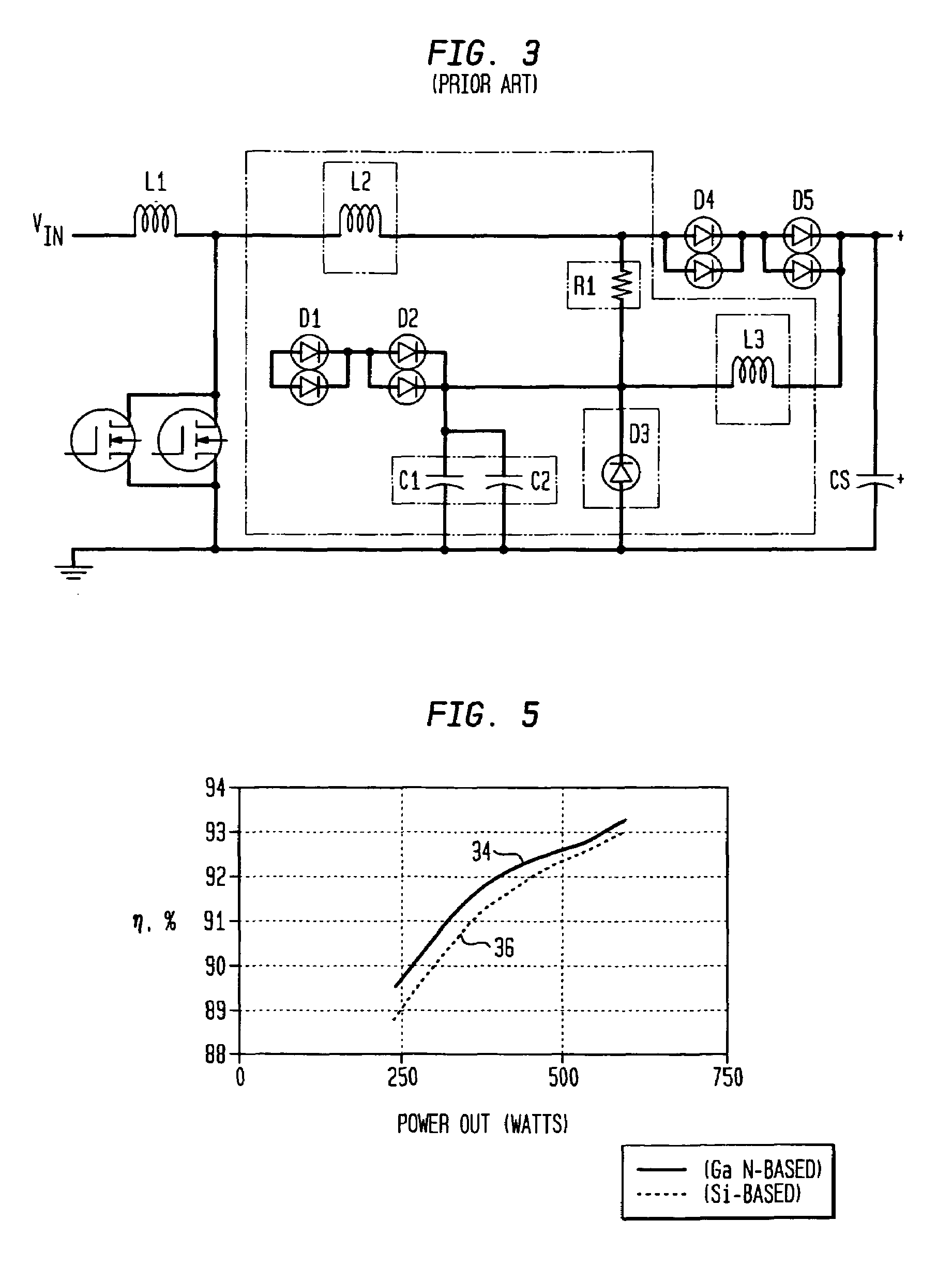
[0018]FIG. 2 depicts a voltage converter 10 under an illustrated embodiment of the invention. Included within the voltage converter 10 may be a rectifier (e.g., a bridge rectifier) 12, an inductor 14, a switching device 18 a diode 16 and an output charge storage device (e.g., a capacitor) 20.

[0019]The rectifier 12 may receive an alternating current (AC) input from an input power source (not shown) and provide a direct current (DC) output. A series connected inductor 14 and switching device 18 may be connected across the output of the rectifier 12. A series connected diode 16 and output capacitor 20 may be connected between a midpoint of the series connected inductor and switching device and terminal of the rectifier output (i.e., in parallel with the switching device).

[0020]The switching device 18 (while being shown in FIG. 1 as being a FET) may be any switching element of reverse conductivity type. Examples of switching elements may include an Insulated Gate Bipolar Transistor (IGB...


PUM


Abstract

A converter is provided having an AC input and a DC output. The converter includes a rectifier that receives the AC input and that provides a rectifier output, a series connected current to magnetic field energy storage device and current interrupter connected across the rectifier output and a series connected gallium nitride diode and output charge storage device connected between a midpoint of the series connected magnetic field energy storage device and current interrupter and a terminal of the rectifier output and wherein the converter is characterized in not needing a transient voltage suppression circuit.

Description

FIELD OF THE INVENTION[0001]The field of the invention relates to power supplies and more particularly to voltage conversion circuits based on gallium nitride (GaN) semiconductor devices.BACKGROUND OF THE INVENTION[0002]Portable power supplies have become an increasingly important part of our society. Examples of where portable power supplies are needed include portable computers, cellular communication devices and video games.[0003]Power supplies for portable devices are typically constructed from silicon semiconductors (e.g., silicon diodes). The pervasive use of silicon diodes, in no small part, is because of the inexpensive manner in which such devices can be fabricated.[0004]While silicon diodes are inexpensive, they also suffer from a number of disadvantages. One of the biggest disadvantages is electrical noise. Silicon diodes, in fact, typically require the use of noise suppression (snubber) circuitry. However, the use of snubber circuitry results in a considerable increase i...

Claims


Application Information

Patent Timeline
Patent Type & Authority Patents(United States)
IPC IPC(8): H02H3/20
CPCH02M1/4225H02M3/155H02M7/2176Y02B70/126Y02B70/1483Y02B70/10
Inventor SHELTON, BRYAN S.PERES, BORISMCGLYNN, DANIEL
Owner POWER INTEGRATIONS INC
Why Eureka
Try Eureka