Location of wireless nodes using signal strength weighting metric

a wireless node and signal strength technology, applied in the direction of navigation instruments, wireless commuication services, instruments, etc., can solve the problems of certain difficulties in locating wireless nodes, weakening the magnitude or power of radio signals as they travel from their source, and reducing the accuracy of location with the error

Active Publication Date: 2006-10-03
CISCO TECH INC
View PDF87 Cites 179 Cited by
  • Summary
  • Abstract
  • Description
  • Claims
  • Application Information

AI Technical Summary

Benefits of technology

[0022]The present invention provides methods, apparatuses, and systems directed to a wireless node location mechanism that uses a signal strength weighting metric to improve the accuracy of estimating the location of a wireless node based on signals detected among a plurality of radio transceivers. In certain implementations, the wireless node location mechanism further incorporates a differential signal strength metric to reduce the errors caused by variations in wireless node transmit power, errors in signal strength detection, and / or direction-dependent path loss. As opposed to using the absolute signal strength or power of an RF signal transmitted by a wireless node, implementations of the present invention compare the differences between signal strength values detected at various pairs of radio receivers to corresponding differences characterized in a model of the RF environment. One implementation of the invention searches for the locations in the model between each pair of radio receivers where their signal strength is different by an observed amount. As discussed in more detail below, the wireless node location mechanism can be incorporated into wireless network environments, such as 802.11 networks, to estimate the location of mobile stations, rogue access points and other wireless nodes.

Problems solved by technology

Generally speaking, the magnitude or power of a radio signal weakens as it travels from its source.
However, the multipath phenomenon encountered in indoor RF environments does present certain difficulties in locating wireless nodes, since reflection and absorption of RF signals affects the correlation between signal strength and proximity.
While the RADAR system works for its intended objective, even in this system, location accuracy decreases with the error in detecting the strength of RF signals.
As discussed below, however, the error injected by errors in signal strength detection can inject large amounts of error in computing the location of a wireless node, especially where the detected signal, at the radio receiver, is weak.
Still further, while the RADAR system allows a mobile station to track its own location, it does not disclose a system that allows the WLAN infrastructure to track the location of wireless nodes, such as rogue access points.
Moreover, individual differences as to how two different wireless nodes detect and report signal strength can cause errors in location, since the Radio Maps assume no error in such measurements.
Still further, while the RADAR system allows a mobile station to track its own location, it does not disclose a system that allows the WLAN infrastructure to track the location of wireless nodes, such as rogue access points.
This paradigm shift, however, presents certain problems.
Estimating location based on signals transmitted by a wireless node, however, can be problematic, since transmit power can vary among wireless device manufacturers, and / or may be individually configured by the mobile user.
Furthermore, these approaches also assume a uniform transmit power for the wireless nodes in light of the fact that legal regulations, as well as current chip set technology, generally places an upper limit on transmit power.
These two assumptions, however, can significantly impact the accuracy of locating a wireless node.
In many situations, however, the measured signal strengths, RSSIap1 RSSIap2, and RSSIap3, do not match the signal strengths recorded in the coverage maps MAPap1, MAPap2, MAPap3 at any one location.
However, a change in the wireless node's transmit power (or, in the RADAR system, inaccuracies in detecting signal strength by the wireless nodes) will adversely affect the accuracy of this metric.
It also creates unpredictable error with changes in transmit power.
Similar problems will occur for a fixed error in the “link or path loss symmetry” where the path loss from access point to wireless node differs from the path loss from wireless node to access point by some fixed amount due to propagation characteristics, vantage point, and the like.
In addition, sources of RF interference typically have unknown transmit powers, and may only partially overlap the frequency band in which wireless nodes operate.

Method used


Image

  • Location of wireless nodes using signal strength weighting metric
  • Location of wireless nodes using signal strength weighting metric
  • Location of wireless nodes using signal strength weighting metric

Examples


Embodiment Construction

A. Wireless Node Location and Signal Strength Weighting Metric

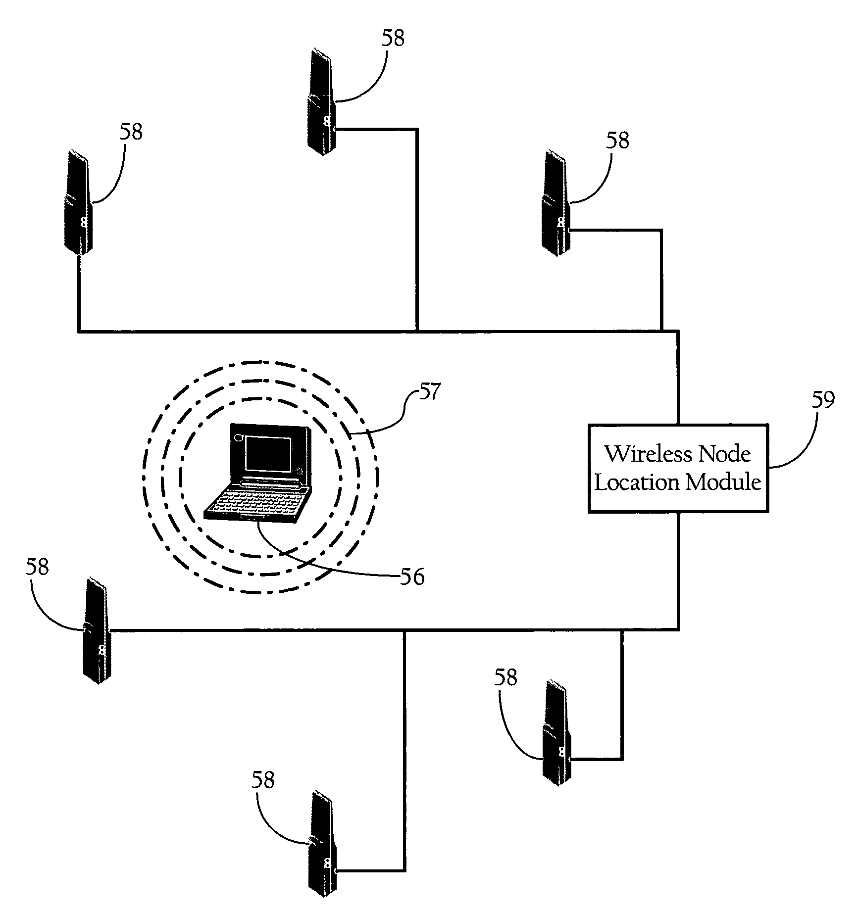
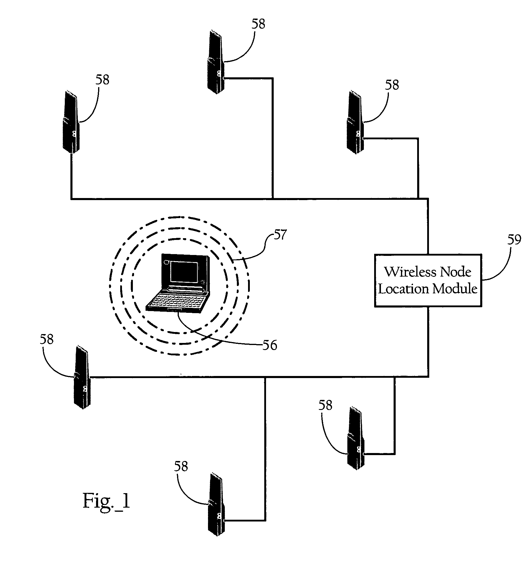
[0028]FIG. 1 illustrates the basic operating components of the wireless node location mechanism according to an implementation of the present invention. As FIG. 1 shows, the wireless node location mechanism includes a wireless node location module 59 and a plurality of infrastructure radio transceivers 58 disposed throughout a physical space. One skilled in the art will recognize that the system depicted in FIG. 1 represents an example of the basic components of the invention and is mostly for didactic purposes. As discussed more fully below, the functionality generally denoted by infrastructure radio transceivers 58 and wireless node location module 59 can be integrated into a variety of systems, such as wireless systems dedicated for location of wireless nodes, or WLAN or other wireless network systems.

[0029]Infrastructure radio transceivers 58 generally comprise at least one antenna, a radio transmit / receive unit, and ...


PUM


Abstract

Methods, apparatuses, and systems directed to a wireless node location mechanism that uses a signal strength weighting metric to improve the accuracy of estimating the location of a wireless node based on signals detected among a plurality of radio transceivers. In certain implementations, the wireless node location mechanism further incorporates a differential signal strength metric to reduce the errors caused by variations in wireless node transmit power, errors in signal strength detection, and / or direction-dependent path loss. As opposed to using the absolute signal strength or power of an RF signal transmitted by a wireless node, implementations of the present invention compare the differences between signal strength values detected at various pairs of radio receivers to corresponding differences characterized in a model of the RF environment. One implementation of the invention searches for the locations in the model between each pair of radio receivers where their signal strength is different by an observed amount.

Description

CROSS-REFERENCE TO RELATED PATENT APPLICATIONS[0001]This application makes reference to the following commonly owned U.S. patent applications and / or patents, which are incorporated herein by reference in their entirety for all purposes:[0002]U.S. patent application Ser. No. 10 / 155,938 in the name of Patrice R. Calhoun, Robert B. O'Hara, Jr. and Robert J. Friday, entitled “Method and System for Hierarchical Processing of Protocol Information in a Wireless LAN;”[0003]U.S. application Ser. No. 10 / 183,704 in the name of Robert J. Friday, Patrice R. Calhoun, Robert B. O'Hara, Jr., Alexander H. Hills and Paul F. Dietrich, and entitled “Method and System for Dynamically Assigning Channels Across Multiple Radios in a Wireless LAN;”[0004]U.S. patent application Ser. No. 10 / 407,357 in the name of Patrice R. Calhoun, Robert B. O'Hara, Jr. and Robert J. Friday, entitled “Method and System for Hierarchical Processing of Protocol Information in a Wireless LAN;”[0005]U.S. patent application Ser. N...

Claims


Application Information

Patent Timeline
Patent Type & Authority Patents(United States)
IPC IPC(8): H04Q7/20G01S19/48G01S5/02H04W64/00
CPCG01S5/0221G01S5/0252H04W4/023H04W4/008H04W64/00G01S5/02213G01S5/02528G01S5/02521
Inventor DIETRICH, PAUL F.DAVI, GREGG SCOTTFRIDAY, ROBERT J.
Owner CISCO TECH INC
Why Eureka
Try Eureka